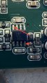
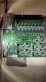
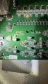
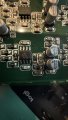
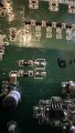
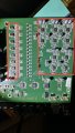
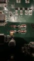
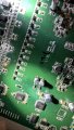
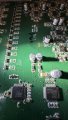
That is a good sign. I wish I knew where that capacitor is connected in the circuit.The measurement across the vacant pads where that cap came from is 8.9 Mohm and 19Mohm when switched the probes.
Is there a way to check for it using continuity and without powering the module?That is a good sign. I wish I knew where that capacitor is connected in the circuit.
Connect one meter lead to one pad and check for continuity with pins 1-8 of the 5532 opamp and with GND (the mounting hole).Is there a way to check for it using continuity and without powering the module?
It means that there is no measurable short under these test conditions.FYI, when I measure the resistance across the other larger caps I removed, they measure OL. Does that mean anything?
ok brbOk. There is one more task before we take a break for the night.
Install the two large capacitors and test the voltages again.
Before you apply power, let me examine your handy work before I give the ok. I need to check that you have soldered the capacitors with the correct polarity. Remember, the black mark on the capacitor is the negative polarity.
When this part is over, you need to buy a 100nF chip capacitor and a new CS5368 chip.
You can install these and repeat the same voltage tests on the two 10R0 resistors.
i powered back up and read the proper voltages at the 10R0 resistors, same as shared before this last step.Looks good. You are good to go.
When this part is over, you need to buy a 100nF chip capacitor and a new CS5368 chip.
You can install these and repeat the same voltage tests on the two 10R0 resistors.
The final verdict is one 10-cent capacitor gave you this big headache.
We don't know what caused this capacitor to go bad. It is not a common failure mode.
We don't know if the CS5368 is damaged or not. At this point it would be wise to install a new one.
Install the replacement capacitor and the new CS5368.
Double check and make sure that there are no shorts between pins when you solder the new CS5368.
If you need tips on how to do this don't be afraid to ask.
(The board will still work without the capacitor.)
Good luck on wrapping up this project.
One possibility is that there is a reference voltage from the CS5368 that has to go to all the 5532JRC to set the DC bias voltage.i powered back up and read the proper voltages at the 10R0 resistors, same as shared before this last step.
the only qusstion I have, is why are the JRCs warming up now when not before. They all have about the same temperature.
notes on the rest.