Need help repairing Allen & Heath Xone:DB4 mixer

Thread Starter

DibElias

Joined Feb 28, 2023
129
We need to see that the analog signals are reaching the CS5368 ICs.
I have an RCA with mp3 play back ready to go.
I confirmed the RCA are delivering signal by plugging them into my sony speaker.

I know I need to plug them into one of the channels on the connector PCB. Then where do I check from there on the Audio IO?

I can check the Connector PCB pins that have a comb connector leaving it into the Audio IO for voltage. However how to check the IC if its receiving the signal?
 

MrChips

Joined Oct 2, 2009
35,030
RCA ANALOG INPUT on CHANNEL 1 and CHANNEL 4 are passive, i.e. no amplification.
Start with CHANNEL 4 for now.

We ought to see signal on CN8 pin-21 (CH4 R) and pin-22 (CH4 L).

Also we want to measure +12V on pins 31 and 33, and -12V on pins 32 and 34.

Allen&Heath XONE DB4 CN5 CN8.jpg
 

MrChips

Joined Oct 2, 2009
35,030
All the 5532 op-amp ICs read 2.05V.
Here is what we know.

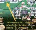
1) The 10R0 resistor is burnt because something else is wrong, not the resistor.
Replacing the resistor will not fix the problem. Something else is already blown.
Replacing the resistor with a new 10Ω resistor only makes the problem worse, i.e. more current is going to flow where it shouldn't be flowing.

2) The 10/16V capacitors are very likely all wired in parallel. Taking a measurement across one capacitor is metering across all capacitors (or at least half the capacitors because there are two supply lines).

3) The +9.52V reading on the replacement resistor is a sure sign of trouble, in multiple ways.
The expected reading should be about -12V. This is clear indication that something is drastically wrong.
On top of that, all the 10/16V capacitors have now been subjected to the wrong polarity and their integrity have been compromised.

4) The voltage of 2.05V on the 5532 op-amps are definitely wrong. We expected to see a positive voltage on pin-8 and an equally negative voltage on pin-4.

At this stage, I would suggest no more testing until we can identify and fix the problems stated in (3) and (4) above.
 

Thread Starter

DibElias

Joined Feb 28, 2023
129
4) The voltage of 2.05V on the 5532 op-amps are definitely wrong. We expected to see a positive voltage on pin-8 and an equally negative voltage on pin-4.
The 2.05v is voltage across.
I remeasured the 5532 op-amps with the black terminal grounded to to ground and used the red probe.
The +ve terminal is reading +11.01V and the other terminal reads +9.56V. In fact, all the pins of all the 5532s read positive voltage and are identical readouts.

1678069672439.png
 

Thread Starter

DibElias

Joined Feb 28, 2023
129
3) The +9.52V reading on the replacement resistor is a sure sign of trouble, in multiple ways.
The expected reading should be about -12V. This is clear indication that something is drastically wrong.
On top of that, all the 10/16V capacitors have now been subjected to the wrong polarity and their integrity have been compromised.
To confirm your understanding is correct.
I did NOT replace the 10R0 reading +9.52V. That is the same resistor I removed earlier, just soldered it back on and tested voltage back to ground.
 

MrChips

Joined Oct 2, 2009
35,030
At this point, we do not know why the resistor is burnt.
Something is taking too much current and we have to find it in order to make any progress. You can take a chance and replace the burnt resistor. Apply power and see what gets hot while you try to take voltage measurements at the two resistors.

What we sometimes do to troubleshoot a problem like this is to use a thermal imaging camera and look for the hot spots.
I would be looking for one of the 10/16V capacitors or one of the 8-pin ICs getting hot.

When you don't have a thermal camera you can use a frost spray. The hot component quickly evaporates any frost coating.
 

MrChips

Joined Oct 2, 2009
35,030
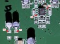
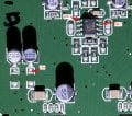
On second thoughts, I am going to suspect one of the 8-pin ICs.
With no power applied and the AC cable unplugged, you will take a resistance measurement between the two resistor pads as follows.

1678071028448.png

Remove both 10R0 resistors.
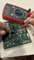
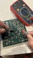
Take a resistance measurement between the top-right resistor pad and the bottom-right resistor pad (i.e. the pads closer to the capacitor). Reverse the meter leads and take a second reading. State the color of the leads for each of the two measurements.
 

Thread Starter

DibElias

Joined Feb 28, 2023
129
At this point, we do not know why the resistor is burnt.
Something is taking too much current and we have to find it in order to make any progress. You can take a chance and replace the burnt resistor. Apply power and see what gets hot while you try to take voltage measurements at the two resistors.

What we sometimes do to troubleshoot a problem like this is to use an thermal imaging camera and look for the hot spots.
I would be looking for one of the 10/16V capacitors or one of the 8-pin ICs getting hot.

When you don't have a thermal camera, you can use a frost spray. The hot component quickly evaporates any frost coating.
Understood.

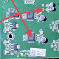
The only hot components on the Audio IO board are the 10R0 resistor and the Cirus Logic 48 pin chip the one closest to the edge.

the op-amp ics are all ambient temp same temp and all read same voltages at their terminals. The capacitors are also not heating up and are at ambient room temp when powered up.
I have a feeling the Sirrus Logic is the issue.
It’s not reading similar voltages at its terminal similar to its twin.
 
Last edited:

Thread Starter

DibElias

Joined Feb 28, 2023
129
RCA ANALOG INPUT on CHANNEL 1 and CHANNEL 4 are passive, i.e. no amplification.
Start with CHANNEL 4 for now.

We ought to see signal on CN8 pin-21 (CH4 R) and pin-22 (CH4 L).

Also we want to measure +12V on pins 31 and 33, and -12V on pins 32 and 34.

View attachment 289009
I confirmed the voltage readouts are correct on pins 31/33 and 32/34.
I also see signal on both channels 1 and 4.
I also see signals at channels 2 and 3 just a much lower readout.
For example CH1 and CH4 read 1800+ microvolt, while 2 and 3 read something like 50 to 70 microvolt. I had to test this voltage using AC voltage. DC voltage did not read anything at any of the channels.
 

MrChips

Joined Oct 2, 2009
35,030
The Cirrus Logic CS5368 does not use +12V and -12V supply. However, it is connected to the op-amps.
The only way you can get +9.52V is from the +12V supply.
Something is creating a low resistance path from the -12V supply rail to the +12V supply rail.
 

Thread Starter

DibElias

Joined Feb 28, 2023
129
Take a resistance measurement between the top-right resistor pad and the bottom-right resistor pad (i.e. the pads closer to the capacitor). Reverse the meter leads and take a second reading. State the color of the leads for each of the two measurements.
Followed these instructions, results below:

Red on top pad
Black on lower pad
Readout 249 Ohm

Switched probe
Readout 124 Ohm
 

Thread Starter

DibElias

Joined Feb 28, 2023
129
Frosty spray? Can you share a link to one with me? Is this the same as the freezing spray?

Yep, I’m gonna get me a pint of ice cream now… it’s worth a break :rolleyes:

at least we have detected something so far.

I sometimes think, why in the world would you be helping me for this long!!? I really appreciate the guidance
 

MrChips

Joined Oct 2, 2009
35,030
The only way you can get +9V on the -12V supply rail is from current flowing from the +12V supply rail.
I am going to put my money on a bad 8-pin opamp IC. The problem is having to locate the bad one out of so many ICs.

Without the circuit schematic we will have to reverse engineer the PCB.
We will narrow down our search to these 10 ICs.

Allen&Heath XONE DB4 004-068 opamps .jpg

Firstly, we need to confirm that the two resistors are responsible for supplying +Vs (+12V) and -Vs (-12V) to all 10 ICs.

With the resistors removed, and no power applied we will look for continuity (close to 0Ω) between +Vs and pin-8 (upper right corner) of each IC. That is sufficient to confirm the +Vs connection.

We can also confirm -Vs connection to pin-4 (lower left corner) of each IC.


Allen&Heath XONE DB4 004-068 opamp power .jpg
 

MrChips

Joined Oct 2, 2009
35,030
After confirming the above tests we will continue to search for a bad IC by measuring the output pin with respect to -Vs as follows:

Again, continuing with no power and the resistors removed,
connect the BLACK meter probe to the -Vs point where the bad resistor used to be as shown.
Using the RED meter probe and the DMM set to measure ohms, measure the resistance at pin-1 and pin-7 of each of the 10 ICs.

There are two measurements for each of the 10 ICs, 20 measurements in total.
We are looking for at least one reading that is substantially lower than all the others.

Allen&Heath XONE DB4 004-068 opamp output pin.jpg
 

Thread Starter

DibElias

Joined Feb 28, 2023
129
Firstly, we need to confirm that the two resistors are responsible for supplying +Vs (+12V) and -Vs (-12V) to all 10 ICs.

With the resistors removed, and no power applied we will look for continuity (close to 0Ω) between +Vs and pin-8 (upper right corner) of each IC. That is sufficient to confirm the +Vs connection.

We can also confirm -Vs connection to pin-4 (lower left corner) of each IC.
I confirmed the +Ves are beeping continuously, and so for the -Ves.
 

Thread Starter

DibElias

Joined Feb 28, 2023
129
After confirming the above tests we will continue to search for a bad IC by measuring the output pin with respect to -Vs as follows:

Again, continuing with no power and the resistors removed,
connect the BLACK meter probe to the -Vs point where the bad resistor used to be as shown.
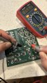
Using the RED meter probe and the DMM set to measure ohms, measure the resistance at pin-1 and pin-7 of each of the 10 ICs.

There are two measurements for each of the 10 ICs, 20 measurements in total.
We are looking for at least one reading that is substantially lower than all the others.
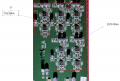
All Pin 1s read the same
All Pin 7s read the same

the two JRC that read lower read the same between both of them. I believe the reading is lower since they are a different type JRC than the ones to the right.
1678123912809.png
 
Last edited:

MrChips

Joined Oct 2, 2009
35,030
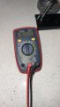
Please post a photograph of the test meter so that I can see the brand name and model, display and range setting.
You should be using the Ohm setting and not the continuity setting for this measurement.
 
Top