Need help repairing Allen & Heath Xone:DB4 mixer

MrChips

Joined Oct 2, 2009
35,026
Each RCA plug has a tip and a shield. Just to baseline what an audio signal looks like, how do I attach the multimeter to it?
Red on the tip and black on the shield?
Yes, normally that is what you would do.
In your case, the DMM is hand-held (it is isolated or "floating") and therefore has no absolute voltage reference.
Therefore it does not matter which way you connect the test leads.
 

Thread Starter

DibElias

Joined Feb 28, 2023
129
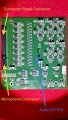
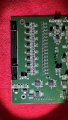
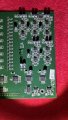
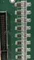
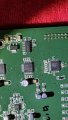
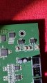
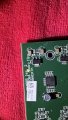
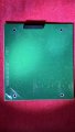
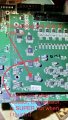
Attached are photos of the Audio IO PCB.

Connected to it are the Back panel Connector PCB (The one with RCA inputs and booth outputs), and the Microphone PCB.
 

Attachments

Thread Starter

DibElias

Joined Feb 28, 2023
129
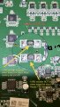
I believe I indicated an issue with the Audio IO board. The 10R0 resistor shared in the previous post and read 139 ohms is super duper hot to the touch when I power the PCB. It being this hot, it is causing the 1st circuit logic chip to be warm, and the next one be hot. See attachment.

My thoughts are order the 10R0 resistor, replace it and see if it solves the issue.
What are your thoughts on this finding?

I’m hoping it did not damage the circuit logic chip.
 

Attachments

MrChips

Joined Oct 2, 2009
35,026
I think you are on to something here.

Allen&Heath XONE DB4 ADC 004-068 .jpg

The two 10R0 resistors supply positive and negative voltages to the circuit.
Apply power and measure the voltages at both ends of each resistor (two readings per resistor).
Keep the black DMM lead on ground and use the red lead to measure the left side of the resistor and again on the right side.
 

MrChips

Joined Oct 2, 2009
35,026
It is too early to jump to any conclusions.

The resistor is getting hot because something down the line is drawing too much current. The resistor is damaged from over heating. Replacing the resistor with a new one will not fix the problem.

I am working on the assumption that this resistor feeds the -12V supply to the opamps. My first guess is that a power supply decoupling capacitor is shorting and needs to be found and replaced.

Why the CS5368 IC is getting hot?
That I do not know. It does not use +12V and -12V supply voltages.
If we have to replace the CS5368 IC it is affordable, about US$30.

Once we have some more clues as to why the resistor is hot and out of spec we still have some analog signals to check.
We need to see that the analog signals are reaching the CS5368 ICs.
 

Thread Starter

DibElias

Joined Feb 28, 2023
129
It is too early to jump to any conclusions.

The resistor is getting hot because something down the line is drawing too much current. The resistor is damaged from over heating. Replacing the resistor with a new one will not fix the problem.

I am working on the assumption that this resistor feeds the -12V supply to the opamps. My first guess is that a power supply decoupling capacitor is shorting and needs to be found and replaced.

Why the CS5368 IC is getting hot?
That I do not know. It does not use +12V and -12V supply voltages.
If we have to replace the CS5368 IC it is affordable, about US$30.

Once we have some more clues as to why the resistor is hot and out of spec we still have some analog signals to check.
We need to see that the analog signals are reaching the CS5368 ICs.
Copy. Makes sense what you said. There must be a reason why that resistor failed. I can’t think of anything I did to make it go bad like that so certainly something cause it to read 140 Ohm instead of 10 Ohm.

I will return to you with the checks you suggested as soon as I can. I have a full day today and tomorrow, the soonest would be Tuesday morning CST.

As for cost of replacing these, OK, just not sure where to send a PCB for repair.
 

MrChips

Joined Oct 2, 2009
35,026
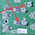
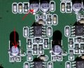
Just to make sure you understand.
The two red arrows are pointing to two examples
I meant, check ALL capacitors that resemble these two.
 

Thread Starter

DibElias

Joined Feb 28, 2023
129
Just to make sure you understand.
The two red arrows are pointing to two examples
I meant, check ALL capacitors that resemble these two.
Copy.

FYI - I ordered 10R0 capacitors they arrive tomorrow.

yep there are many of them on the board.
If I recall correctly, I inspected them with a bright light and did not see anything abnormal.
I’ll i spect all of them again and record voltage across its terminals when powered on. I’ll review how to to check capacitors and do that too.

https://www.fluke.com/en-us/learn/blog/digital-multimeters/how-to-measure-capacitance
 

MrChips

Joined Oct 2, 2009
35,026
Copy.

FYI - I ordered 10R0 capacitors they arrive tomorrow.

yep there are many of them on the board.
If I recall correctly, I inspected them with a bright light and did not see anything abnormal.
I’ll i spect all of them again and record voltage across its terminals when powered on. I’ll review how to to check capacitors and do that too.

https://www.fluke.com/en-us/learn/blog/digital-multimeters/how-to-measure-capacitance
You meant 10R0 resistors. I hope you ordered the right wattage.
You do know that you cannot always measure components correctly, resistors and capacitors, while they are still on the circuit board.

Don't waste your time trying to measure capacitors soldered in-circuit.

We will be looking for a shorted capacitor shortly. This is not going to be easy.
 

Thread Starter

DibElias

Joined Feb 28, 2023
129
Correct 10R0 resistors.
This is the link to it on amazon
How to determine what Watt rating it is?
All it says on is 10R0 and the one I purchased looks like it both in color and size.

Ok. Do you recommend I change it out before I test again? I’m concerned the heat would burn a subsequent micro chip in its circuit.
 

Thread Starter

DibElias

Joined Feb 28, 2023
129
I desoldered both the 10R0 resistors shown in the picture. The one that read 10ohm on the board, read 10.7 ohm off the board. The one that read 139 ohm on the board is reading 263 ohm off the board.

I visually checked all the capacitors on the Audio IO and the motherboard, no signs of bulging or abnormality.
I also used the DMM short circuit beep functio and tested all of the capacitors on both boards, no beeps found. I made sure I wiggles the probes to touch the capacitor terminals not just the solder.
 

Attachments

Thread Starter

DibElias

Joined Feb 28, 2023
129
I’m re-attaching the resistors.
I did jump to conclusions and removed to replace both of them anyway thinking that was the end of the root cause analysis.
My bad.
They are resoldered on and checked to make sure the terminals are fully intact reading resistance across.
 
Last edited:
Top