Ok, so I soldered in a diode on the positive leg coming from the 9 volt bat, got rid of the potentiometer, and still tested the same. So I guess the feedback network is not working?
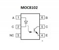
Sorry Timescope, I drew the pics incorrectly. Yes pin 4 and 6 should be switched. That is how I tested. I just had it backwards when I drew that in paint program. Pin 5 goes to pin 1 on U3. So sense I tested it correctly, where does that leave me?
Ok, I'll try that tomorrow. Question about the voltage, if 10.19 volts is what's needed, what does adding a 1kohm resistor do or change vs the diode? What raises the voltage to 10.19 to test it correctly? Or am I to use a 12v battery?
I have some auto 12v battery's, I have 12vdc 1amp trickle charger, I have 18v lithium battery's from my Makita cordless drills. I have a bunch of dc wall plug transformers, I can check for a optimum voltage range if that helps.
one tester I had .600 mv and when battery is connected it goes down to .143 mv
second tester .985mv down to .147 mv
So does 1.47= continuity? I thought it would show OL or 000 if there was continuity
I found an 1kΩ resistor on an scrap board I had brown,black,red,gold which should be a 1kΩ resistor. I checked with meeter to confirm and it was correct.
What is the best way to remove it? I have a digital 80 watt solder station with a fine point and also a bunt point tip. I have a few other cheaper irons and a desolder iron with a bulb that sucks up solder.
I usually apply solder to all the pins on one side of the ic, then try to lift that side of the ic up with a small precision screwdriver while heating all the pins simultaneously. You have to do it quickly to avoid overheating the ic.
Ok did what you said and it came off real easy. Traces didnt lift and didn't overheat u3. I redid the test and now there is continuity all the time with out the battery connected.
 Facebook
 Google
 GitHub
 Linkedin