Need help dissipating more power with transistors!

bug13

Joined Feb 13, 2012
2,002
Bug13: Hm that's interesting. Good point. I forgot about varying the duty cycle haha. Would I use a 555 to do the PWM? Either way.. How would I do it? I'd like to see what I can get.
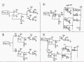
I would just use an MCU with a logic level mosfet. Low pass filter the music, then feed it to ADC of the MCU, then output a PWM to drive a logic level mosfet.

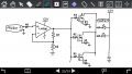
Or you can have a look at this, I think it should work, but I haven't tested it myself.
http://www.pcbheaven.com/circuitpages/Voltage_Controlled_PWM_Generator/
 

Thread Starter

Konduction2

Joined Feb 12, 2014
52
Bug13: okay thanks for the link! I'm not going to use an MCU though because I am deliberately trying to do everything analog, as I don't want to use the MCU knowledge I already learn in class haha.
 

#12

Joined Nov 30, 2010
18,224
Doing a crude estimate...
Total gate charge = 71 nanocoulombs @ 10 Vgs.
100 ohms x 71e-9 = 71e-7 for the RC time constant.
Assuming 5 time constants to fill a capacitor by 90%, time = 35.5 useconds.
Invert gives 28 kiloHz for one rise or fall time.
14 KHz for 2 rise and fall times.
Not fast enough! At 14KHz the mosfet will be spending all of its time in transition.
Better drop the resistor by a factor of 10.

Got an idea how this works now?
 

bug13

Joined Feb 13, 2012
2,002
Doing a crude estimate...
Total gate charge = 71 nanocoulombs @ 10 Vgs.
100 ohms x 71e-9 = 71e-7 for the RC time constant.
Assuming 5 time constants to fill a capacitor by 90%, time = 35.5 useconds.
Invert gives 28 kiloHz for one rise or fall time.
14 KHz for 2 rise and fall times.
Not fast enough! At 14KHz the mosfet will be spending all of its time in transition.
Better drop the resistor by a factor of 10.

Got an idea how this works now?
You don't need to convert charge (Q) to capacitance (C) ?
 

#12

Joined Nov 30, 2010
18,224
Grrr. Missed again. :mad:

Hang on while I try getting my brain in gear.

Ciss = 1960pf
RC = 1960 e-12 x 100 ohms is 1.96 e-7
5RC = 9.8 e-7
invert = 1 MHz
and that is plenty fast enough for audio work.
Darn senior moments. :(
 

Thread Starter

Konduction2

Joined Feb 12, 2014
52
#12: wow, thanks so much! Nice to know how to mathematically calculate my values! I will reference this after I solve some of my more pressing issues.

Soo, sorry everyone for the second time about my super slow response - been swamped with work. I've implemented the parallel MOSFETs and everything NEARLY works! I have one problem though. My lights synchronize well for everything except the bass. Bass notes (I would guess 100Hz and below) do not activate my lights. I have attached my schematic - help me find the pesky high pass filter! Oh and I should mention that it must be something related to the MOSFETs (IRF540n), because if I simply remove all of them and replace them with a single BJT (TIP31c), (and I do absolutely nothing else to my circuit) then everything works fine. Help pleasee!

Schematic labels:
- R0 = 0 ohms
- R1 = 20K ohms
- R2 = 10,000K ohms
- R3 = 100 ohms
- R4 = 0 ohms

There are a few other mysteries about my circuit that I want to ask about, but I'd like to first figure out why using MOSFETs make my lights not respond to bass notes.
 

Attachments

Alec_t

Joined Sep 17, 2013
14,337
With R1 =20k the amp gain is only ~1.4. According to the LM386 datasheet "the amplifier is only compensated for closed-loop gains greater than 9". The high capacitive load presented by the FET gates may therefore be causing instability, perhaps giving the observed effects at low frequencies. What is the purpose of R2? It is in parallel with ~50k so will have little effect. Check the datasheet re gain control, which is usually done using pins 1 and 8.
 

Thread Starter

Konduction2

Joined Feb 12, 2014
52
Alec_t: ? Isn't the gain supposed to be (R1+R2)/R2? Meaning my gain is pretty much just 1. What does compensated mean? Shouldn't the gate capacitance cause a low pass filter instead of a high pass filter? How is R2 in parallel with 50k - where did you get 50k? To be honest, I don't know where you got a gain of 1.4 either.
 

bug13

Joined Feb 13, 2012
2,002
The gain control of lm386 is controlled by putting a resistor between pin 1 and pin 8, it can be adjust between 20-200. I think you mistaken it as a regular opamp.
 

Alec_t

Joined Sep 17, 2013
14,337
Isn't the gain supposed to be (R1+R2)/R2?
Not for the LM386 (which isn't a standard opamp). You need to account for 50k in parallel with R2. So the gain is effectively (20k + 50k)/50k = 1.4.
where did you get 50k?
From the schematic in the datasheet. Have you read it?
What does compensated mean?
It means that within the specified limits the amp phase response is such that the amp is stable.
 

Thread Starter

Konduction2

Joined Feb 12, 2014
52
...Whaaat. -_-
So I've been using the lm386 incorrectly for a whole year... that would actually explain a loot of mysteries haha. Thanks guys, my stupidity is slowly diminishing piece by piece.

Okay. I will try again and get back to you guys. In the meantime though, I have another question. If I connect two lm386's to my music signal, and then have one output to the gate of a MOSFET and have the other output to the base of a BJT, will the MOSFET and the BJT show symptoms of being in parallel? Assume everything shares the same power source and ground.
 

Alec_t

Joined Sep 17, 2013
14,337
will the MOSFET and the BJT show symptoms of being in parallel?
Unless you drive the BJT base via a suitable resistor and ensure the rated Vgs of the MOSFET is not exceeded the main symptom will be a column of magic smoke :). Exactly what symptoms did you have in mind?
 

BobTPH

Joined Jun 5, 2013
9,003
MOSFETs in parallel are fine as long as you are using them as switches. In your application, not so good.

For that kind of power, I would convert the incoming signal to a PWM signal then drive the lights through a MOSFET. When operated as a switch they will be able to handle much more power.

Bob
 

Thread Starter

Konduction2

Joined Feb 12, 2014
52
Sorry, I've realized what I'm trying to ask is complicated so I've broken it down into questions (1) and (2). I've also added some more questions that I really need help with, so I'll probably need help from more people haha. Each of my questions will refer to one of four schematics that I've drawn and attached. I had noooo idea that simply trying to dissipate more power to synchronize more lights would be so difficult.

Regarding schematic A:
1) I have implemented this schematic before and ran into a confusion. Based on the brightnesses of LED1 and LED2, I deduced that the two transistors (both BJTs, TIP31c specifically) were showing "symptoms" of being in parallel. Why is this? (NOTE: I am Not asking to know the proper way to put BJTs in parallel, but rather why this way didn't work!)

To elaborate: I would expect LED1 and LED2 to be the same brightness. However, LED1 is always significantly brighter than LED2, showing that the transistor, T1, is hogging current from the other transistor, T2, as if they were in parallel. Why is this happening? I understand that the transistors' base and collector are in parallel, but their load is not. In a complete parallel configuration, a BJT will start dissipating more current than the others because tiny inequalities for one BJT => more current => more heat => more current => etc until so much of the load is powered by that one transistor that the transistor blows up. BUT in this circuit, each BJT gets its own separate load to power so one BJT can't keep powering more and more of the load such that other BJTs don't have to supply as much current. The problem is that I have observed this to happen. If I unplug the hotter BJT, then the LEDs powered by the other BJT will get brighter - why?

Regarding schematic B:
2) Will the "symptoms of being in parallel" as mentioned in (1) still happen with this circuit? (assume R1 = R3 so op-amp gains are same)

Regarding schematic C:
**I understand I misused the 386 as a normal op-amp, but I will set that error aside for now**

3) My R0 is zero. Should I have a resistor there? Why or why not?

4) My D0 is also absent, but I've heard I should have a diode there for my parallel MOSFETs. Is there a particular diode I should use and why?

5) Without the CCFL (actually a 680V power inverter which then powers a CCFL) shown in the top right, my LEDs are dim even when there is no music playing. Putting the power inverter there fixes this (lets my lights turn off). Why does the inverter fix this? Voltage drop across my LEDs are 7.35V without the inverter and 1.4V with it. I can bring it down to .75V by adding two more inverters in parallel. The connection of the CCFLs to the inverter makes no difference.

6) When R1 = R2 = 9M ohm, C0 > 220 uF, 12V is from my computer's nice 650W PSU, my lights synchronize really well. But if C0 = 0, then my lights just stay on even with no music, even after I power cycle my whole circuit, until I put the capacitor back in. Why is this? And also my speakers output a ton of static when C0 = 0; why is this? (my speakers and the LM386 share the same audio signal via a Y-splitter plugged into my PC headphone jack).

7) With R0=0, R1 = R2 = 9M ohm, R3 = 100 ohm, R4 = 0, C0 = 470 uF, this is my current setup. And my lights synchronize really well. However, my speakers are quite static-y while playing music unless I disconnect the audio signal from my LM386 (it shares the audio signal with my speakers via a Y-splitter) or I unpower my circuit. There is no static when I use a BJT instead of MOSFETs. Why is my circuit putting noise into my audio signal and how do I fix it without switching back to BJT? If the solution involves having an R0, are there alternate solutions?

Regarding schematic D:
8) It seems MOSFETs are easily affected by electromagnetic waves. If S0 is open and S1 is closed, then while LED1 is synchronizing perfectly to music, LED2 will synchronize poorly and very dimly (much brighter if I add more MOSFETs in parallel with T2). And if I am not even playing music, then turning on my air conditioning will cause LED2 to brightly flash (but not LED1, since T1 is a BJT). Realistically, is it feasible to stop this by using paper clips to make Faraday cages around my MOSFETs? Is there another way I can stop this? I'm getting flashbanged every time someone turns on a big appliance haha.
 

Attachments

Thread Starter

Konduction2

Joined Feb 12, 2014
52
Alec_t: Are you saying that there is no effective difference between each transistor having its own op-amp vs both sharing one op-amp?

BobTPH: I don't think the problems I'm having would be fixed with a PWM. I want to use MOSFETs in parallel so that I can always adjust how much load I can support without having to buy different MOSFETs.
 

bug13

Joined Feb 13, 2012
2,002
that's a lot of question, but I will just stick to A.

  • Your leds need to be on collector side, not the emitter side.
  • you needs two resistors on the base of the BJTs.
  • What is " 'symptoms' of being in parallel"?
The reasons that your circuit doesn't work could be a combination of the following reasons:
  • mismatch of BJTs at the PN junction (they will all always be mismatched)
  • Wrong BTJ configuration choice (as of my first and second point)
  • BJT doesn't have a fix gain, you need to setup up a simple fix gain BJT amp.
Read this before you try using MOSFET and take a second look on your other questions. And would be a good idea to take a look at PWM design again.
 

Thread Starter

Konduction2

Joined Feb 12, 2014
52
Bug13:
-Why?
-Why? I thought it's only necessary if the BJTs are in parallel..
-The "symptom" I mention is the ability of one transistor to influence how much power is dissipated by another transistor

-This wouldn't explain why one BJT affects the other though, right?
-Well I know it's wrong because it doesn't work haha
-Ohh interesting, thanks! I'll have to learn how to do that

Ah thanks, but I'm already well acquainted with all that. I've also already been mostly successful with my MOSFETs. There are just some really specific questions that I still can't answer, despite spending all week narrowing down my question list. At this point, there would be no reason for me to use PWM - my MOSFETs are not having trouble with dissipating power.
 
Top