Necessary steps to design Mini Audio Amplifier Circuit With BC547

Thread Starter

anhnha

Joined Apr 19, 2012
905
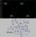
Below is the Mini Audio Amplifier Circuit With BC547. All components with their values are available but assume that I want to calculate and design from from scratch what necessary steps should I do?
First for battery, I'll pick 3V.
The first stage is a common emitter with gain Rc/re with re = 25mV/Ic.
Second stage is also common emitter with PNP transistor.
The third stage is a push-pull to drive load.
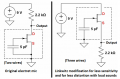
Assume that I use this Electret Condenser Microphone how do you assign gain and bias current for each stage?
What step should I do in order to calculate value of each component and make it work?

1572730792389.png

Link: http://diy.slmelectronic.co.uk/electronic/Mini-Audio-Amplifier-Circuit-With-BC547
 

MrChips

Joined Oct 2, 2009
30,712
Before you can design a multistage audio amp you need to learn how to design a single transistor common emitter amplifier. Also learn the difference between common base, common emitter and common collector configurations.
There are many tutorials available on the internet.
 

ci139

Joined Jul 11, 2016
1,898
what you must understand here is that
this is a battery powered app
the battery AA AAA (*depending on model/manufacturer) has it's (unloaded) useful voltage from
1.42 to 1.68 Volts *fresh
1.14 to 1.27 Volts *becoming empty (providing tens of mA under continuous load)
0.85 to 1.13 Volts *near empty (not providing over 1.3mA under continuous load)
so your design should work in rough scale from 3.1V(2x330mΩ) down to 1.2V(2*3.3Ω) // ← unloaded terminal voltageV (internal resistanceΩ of the battery)
The lower usable limit depends on your application demands since ↑ the more empty the battery the more sensitive to load it becomes

recommended but not a must (e.g. use any time you need "something that works" instead of something to "work out") :
when designing op amps there are 3 limits 2.16V , 6.8V & 9.6V total supply at which there seem to be a step at common mode and frequency responce ← what that roughly means is "you want" to keep your (loaded) batter voltage above 2.16V --or-- to avoid complex and/or tight tolerance design use 4x AA(A) 6V // 6xAA(A) 9V // or better 8xAA(A) 12V option . . . since your speaker is 8Ω the 6V option may be preferred - enabling to use a ±3V bipolar supply . . . about http://schematicblog.blogspot.com/2011/08/tda2006-12w-audio-amplifier-circuit.html ← the numbers seem to be correct but :
Vs Supply Voltage ± 6 ± 15 V so it requires a higher supply voltage and may be a "overshot" for your requirements
 
Last edited:

Marley

Joined Apr 4, 2016
502
assume that I want to calculate and design from from scratch what necessary steps should I do?
First would be to determine the output voltage level of the microphone and the input impedance it requires.
Then determine output level required into the earphone or speaker and the impedance of this device. From this you can work out the overall gain required. Also, the output level might determine the supply voltage required and/or the type of circuit driving the output.

The circuit in your post is a very basic standard design - nothing wrong with that. The circuit in Bordodynov's post is slightly more sophisticated. Once you have chosen a design, component values can be roughly calculated with ohm's law, transistor current gain figures (from the datasheets) and basic knowledge of transistor operation. For example that the base-emitter voltage is about 0.65V.

Because there is DC negative feedback around the amplifier (the 8k2 in your circuit) the design should be fairly tolerant of component values. If with no audio signal the voltage at the junction of the two emitters at the output is approx half the supply voltage, it is probably working correctly. This is ultimately set by the voltage on the base of the first transistor which will be 0.65V higher than its emitter which is set by the feedback resistor and emitter resistor divider. This base voltage is set by the voltage divider 120k, 47k and 330R. Often good at the start to consider what DC voltages you expect at various points around the circuit and knowing the currents, calculate the resistor values from that.

You might start with a simple standard design and find it can't deliver the gain and output power you require. Then you would have to go back and change the circuit for a more complex design.
 
Last edited:

Audioguru again

Joined Oct 21, 2019
6,673
The original design has many errors. I show its simulation with severe distortion even at low output levels.
I changed a few things and it got better.
I changed many things and it is the best.
Because your battery is only 3V when new and its voltage drops when it is used then this amplifier will not be loud before it produces clipping distortion.
 

Attachments

Audioguru again

Joined Oct 21, 2019
6,673
I have never seen before an electret mic connected backwards as it is in these circuits. Its "ground" and metal case are used as the signal output. Then the Jfet in it is a follower with no voltage gain.
Actually, the backwards mic will probably have NO OUTPUT since the Jfet source wire is connected to the ground side of the mic element which cancels the signal.

Usually, an electret mic is used with its case and ground connection connected to the cable shield and signal ground, then its Jfet drain connection has a drain resistor and output signal with some voltage gain.
There is a modification for an electret mic that is inside a musical instrument where the source of the Jfet is its output for very loud sounds to have low distortion.
 

Attachments

Bordodynov

Joined May 20, 2015
3,177
I used an electret microphone in this non-standard power-on. Usually an electret microphone has 2 pins. And it is a two-pole device. In fact, it is a DC and AC power source. Two different switching on of the microphone have different phases of the output signal, but the output signal is the same. 2019-11-06_09-32-04.png
 
Last edited:

Thread Starter

anhnha

Joined Apr 19, 2012
905
hi, everyone presented great circuits but I still not sure how to calculate it.
Let's assume that the voltage battery is 3V. Microphone outputs a sine wave with amplitude 15mV and the load is 32 ohms, 20mW.
I calculated DC voltages at nodes.
what should I do next?
Also what's the function of 330R resistor?

1573068936416.png
 

ci139

Joined Jul 11, 2016
1,898
the 2-20mV is the resulting voltage "disturbance"/induction from the air pressure change
otherwise the electret (depending on type) drops 1.5 to 4.5 V and has apropriate DC resistance apx. 3 to 1 kΩ
so your DC biasing chain looks like +Vcc - [330R] (1k7) [10kΩ] - Vee -- e.g. -- 3V/12kΩ = 250µA ← should be greater equal 500µA = 6k8 in parallel with 10k pot. or replace it with 3k3 and 620R to 750R in series ←← this gives you better DC bias for electret

for input amplifier use http://www.guitarscience.net/calcs/ce.htm (by https://www.google.com/search?q=CE+amplifier+bipolar+stage+calculator+online) , etc. . . .
 

Thread Starter

anhnha

Joined Apr 19, 2012
905
the 2-20mV is the resulting voltage "disturbance"/induction from the air pressure change
otherwise the electret (depending on type) drops 1.5 to 4.5 V and has apropriate DC resistance apx. 3 to 1 kΩ
so your DC biasing chain looks like +Vcc - [330R] (1k7) [10kΩ] - Vee -- e.g. -- 3V/12kΩ = 250µA ← should be greater equal 500µA = 6k8 in parallel with 10k pot. or replace it with 3k3 and 620R to 750R in series ←← this gives you better DC bias for electret

for input amplifier use http://www.guitarscience.net/calcs/ce.htm (by https://www.google.com/search?q=CE+amplifier+bipolar+stage+calculator+online) , etc. . . .
That doesn't help much because it requires you to enter Rc, Re. But how do you determine those resistor values and currents in the first place?
 

Audioguru again

Joined Oct 21, 2019
6,673
In post #6 I showed a simulation of the circuit that does not work because its output is severely distorted. I showed fixes that make it better and best.

Without the 330 ohm resistor then when the battery becomes a little weak then its voltage jumps up and down with the signal and it feeds directly into the microphone and input bias resistors causing oscillations. With the 330 ohm resistor and the 47uF capacitor to ground filtering its voltage then there are no oscillations.
 

Thread Starter

anhnha

Joined Apr 19, 2012
905
In post #6 I showed a simulation of the circuit that does not work because its output is severely distorted. I showed fixes that make it better and best.

Without the 330 ohm resistor then when the battery becomes a little weak then its voltage jumps up and down with the signal and it feeds directly into the microphone and input bias resistors causing oscillations. With the 330 ohm resistor and the 47uF capacitor to ground filtering its voltage then there are no oscillations.
Can you show how to calculate component values?
 

Audioguru again

Joined Oct 21, 2019
6,673
Resistor values depend on the spec's of the circuit (power output, load impedance, power supply voltage, amount of distortion, datasheet spec's for the transistors and Ohm's Law.
Capacitor values depend on the lowest frequency you need to pass, the highest frequency you need to pass and the amount of ripple from the power supply or battery.

Recently you said the supply is 3V and the load is 32 ohms/20mW. Then the output must be 0.895V RMS which is 2.53V peak-to-peak.

The output emitter-followers each produce a voltage loss of about 0.8V so the maximum undistorted p-p output swing is 3V - (0.8V x 2)= 1.4V so the output power into your 32 ohms load is (1.4V/2.828) squared/32 ohms= 7.66mW. Your power supply voltage of only 3V is too low to produce 20mW.

For the fixed amplifier to produce undistorted 20mW into 32 ohms then the amplifier output will be 2.53V peak-to-peak as shown above plus the 0.8v of loss from each output transistor. 2.53V + 1.6V= 4.13V is the power supply voltage needed.
 

Thread Starter

anhnha

Joined Apr 19, 2012
905
Recently you said the supply is 3V and the load is 32 ohms/20mW. Then the output must be 0.895V RMS which is 2.53V peak-to-peak.
How do you get those numbers?
From my calculation it's 0.8V RMS and 2.26V peak-to-peak.

The output emitter-followers each produce a voltage loss of about 0.8V so the maximum undistorted p-p output swing is 3V - (0.8V x 2)= 1.4V so the output power into your 32 ohms load is (1.4V/2.828) squared/32 ohms= 7.66mW. Your power supply voltage of only 3V is too low to produce 20mW.
It seems that you made a mistake there. Why 2.828 not 1.414?
The output power is (1.4/1.414)^2/32 ohms = 30mW
 
Top