 Facebook
 Google
 GitHub
 Linkedin
I'm working on a system to monitor my sump pit, using a raspberry pi. I have a ADS1115 adc board hooked up to read in analog voltage from various sensors. One channel of the ADS1115 monitors the 5v into the raspberry pi. I am powering the pi by back feeding 5v into the expansion header and want to keep an eye on the voltage.
I use a voltage divider to divide the 5v in half, to bring it within the range of the ADS1115 (max voltage it can read is 3.3v). It was working fine, reading a nice solid 2.52 volts. Then when I checked it again 5 minutes later it was reading a fluctuating value of 2.8 - 3.2! I was not near the board at this time, I was monitoring the data remotely from my desktop computer through an SSH session.
I immediately went downstairs and put a DVM on the 5v pin - it reads a steady 5.04v. I measured the pin on my ADS1115 adc - indeed it is fluctuating between 2.8 and 3.2. Do you think one of the resistors might have gone bad? I can't remember what value I used, I think they were 1k or 2k or something like that. My first thought is to power everything down, disconnect the expansion cable, and measure the ohms of the resistors. Like I said it was working perfectly, so I know I used the same value for each one. I'm pretty new to building circuits so wanted to ask if there was anything obvious I might be missing. Thanks.
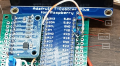
Here is some output from the 3 inputs I have connected to the ADC. Channel 0 is the 5v voltage divider.
I use a voltage divider to divide the 5v in half, to bring it within the range of the ADS1115 (max voltage it can read is 3.3v). It was working fine, reading a nice solid 2.52 volts. Then when I checked it again 5 minutes later it was reading a fluctuating value of 2.8 - 3.2! I was not near the board at this time, I was monitoring the data remotely from my desktop computer through an SSH session.
I immediately went downstairs and put a DVM on the 5v pin - it reads a steady 5.04v. I measured the pin on my ADS1115 adc - indeed it is fluctuating between 2.8 and 3.2. Do you think one of the resistors might have gone bad? I can't remember what value I used, I think they were 1k or 2k or something like that. My first thought is to power everything down, disconnect the expansion cable, and measure the ohms of the resistors. Like I said it was working perfectly, so I know I used the same value for each one. I'm pretty new to building circuits so wanted to ask if there was anything obvious I might be missing. Thanks.
Here is some output from the 3 inputs I have connected to the ADC. Channel 0 is the 5v voltage divider.
Code:
CH_0 = 2.92 V | CH_1 = 2.158 V | CH_2 = 0.376 V
CH_0 = 2.93 V | CH_1 = 2.158 V | CH_2 = 0.376 V
CH_0 = 2.88 V | CH_1 = 2.158 V | CH_2 = 0.376 V
CH_0 = 2.89 V | CH_1 = 2.158 V | CH_2 = 0.376 V
CH_0 = 2.91 V | CH_1 = 2.158 V | CH_2 = 0.377 V
CH_0 = 2.92 V | CH_1 = 2.158 V | CH_2 = 0.377 V
CH_0 = 2.85 V | CH_1 = 2.158 V | CH_2 = 0.377 V
CH_0 = 2.86 V | CH_1 = 2.158 V | CH_2 = 0.377 V
CH_0 = 2.88 V | CH_1 = 2.158 V | CH_2 = 0.377 V
CH_0 = 2.89 V | CH_1 = 2.158 V | CH_2 = 0.377 V
CH_0 = 2.93 V | CH_1 = 2.158 V | CH_2 = 0.376 V
CH_0 = 2.86 V | CH_1 = 2.158 V | CH_2 = 0.376 V
CH_0 = 2.88 V | CH_1 = 2.158 V | CH_2 = 0.376 V
CH_0 = 2.87 V | CH_1 = 2.158 V | CH_2 = 0.376 V
CH_0 = 2.84 V | CH_1 = 2.158 V | CH_2 = 0.377 V
CH_0 = 2.83 V | CH_1 = 2.158 V | CH_2 = 0.377 V
CH_0 = 2.89 V | CH_1 = 2.158 V | CH_2 = 0.377 V
CH_0 = 2.85 V | CH_1 = 2.158 V | CH_2 = 0.378 V
CH_0 = 2.88 V | CH_1 = 2.158 V | CH_2 = 0.378 V
CH_0 = 2.88 V | CH_1 = 2.158 V | CH_2 = 0.378 V
CH_0 = 2.86 V | CH_1 = 2.158 V | CH_2 = 0.378 V
CH_0 = 2.87 V | CH_1 = 2.158 V | CH_2 = 0.378 V
CH_0 = 2.93 V | CH_1 = 2.158 V | CH_2 = 0.377 V
CH_0 = 3.07 V | CH_1 = 2.158 V | CH_2 = 0.377 V
CH_0 = 2.89 V | CH_1 = 2.158 V | CH_2 = 0.377 V
CH_0 = 3.04 V | CH_1 = 2.158 V | CH_2 = 0.377 V
CH_0 = 2.87 V | CH_1 = 2.158 V | CH_2 = 0.376 V
CH_0 = 2.91 V | CH_1 = 2.158 V | CH_2 = 0.377 V
Attachments
-
 1.3 MB Views: 9


