 Facebook
 Google
 GitHub
 Linkedin
Props to Coquellicot and sorry for discounting what you said.Wow.... you guys are next level. I’m still working on calculus to get my associates. What does a synchronous rectifier entail. Watch the video I posted and see what you think about it.
MOT power supply
- Thread starter Hutch2793
- Start date
Scroll to continue with content
MisterBill2
- Joined Jan 23, 2018
- 27,639
The big concern with alternator diodes is that they are rated in an "air-over" application, which means that when that alternator is delivering 100 amps at 3500 alternator RPM and the engine turning about 1750 RPM, there is a very strong wind blowing on those diodes and the heat sink area. So if you used a motor driven alternator for your power supply you would be OK. But that is not the situation. The diode is on some sort of heat sink and there may be a small fan and the air moving a bit. But not the same. At one time I got some sample diodes from a Motorola sales guy, and he explained that they were good for 60 amps in an alternator or SIX amps mounted with #14 wire leads in a power supply. So cooling air matters a lot.
There are some really good diode application notes around from back when these power diodes were new things, and all that information is still valid, although the part numbers are changed.
There are some really good diode application notes around from back when these power diodes were new things, and all that information is still valid, although the part numbers are changed.
MisterBill2
- Joined Jan 23, 2018
- 27,639
Yes, two windings of about 7 volts each, OR one 14 volt winding with a tap connection in the center. The principle of operation is that, referenced to the center, only one end at a time is positive, and only when the end of the winding is positive will the diode conduct. So there would only be two diodes, one connected at each end, and the diodes will be taking turns supplying the +7volts to the filter. Yes, winding the transformer gets a bit more complicated, but the cost for diodes is half as much as for a bridge rectifier setup, AND there is inly one diode drop instead of two. I hope that this makes some sense. It has been a while since I wrote detailed descriptions of how stuff works. But the really detailed description helps the service tech fix a system without having to call me and that makes them happy and both of us look good.I agree with you Mr.Bill, even though my .02 cents weighs about as much as a penny. I want to reiterate that I have seen this done with my own eyes with the list of Constants I provided above. This setup ran for 150+ hours sometimes. Cooling a system and making it safe is the easiest part of any project similar to this. I appreciate your input Co and honestly I don’t know enough to say your right, or your wrong. I do know that I don’t want fire, but I also know that what I’m talking about doing and the way I’m going to do it will not spontaneously combust without warning. I will watch for the warnings and plan for that contingency.
Mr.Bill I like where you were going. Let me recap, I need two windings (secondary) that output 14 volts total? You believe that the alternator diodes are not a great route, can you expand on rectification and filtering, please. Everyone else is welcome as well, maybe the secondary smoothing is still an option, or is co correct about that being a bad idea?
I apologize for the mistakes in my writing I’m working at the same time.
One big deal thing is to keep whatever you are electrolzing separated from the power system because corrosion is bad for everything.
MisterBill2
- Joined Jan 23, 2018
- 27,639
And how heavy will the pieces be? A 36 volt 20 amp cheap junk batthery charger for a "golf cart" vehicle only weighs about 27 pounds. And it is about as ugly as an inanimate object that size can be after 15 years in a leaky shed. And pay very close attention to the capacitor connections because the ripple current can cause heating and that can lead to capacitor failure and those capacitors are expensive.
Did you watch that video and see how it was done? I would obviously put a fan on them.The big concern with alternator diodes is that they are rated in an "air-over" application, which means that when that alternator is delivering 100 amps at 3500 alternator RPM and the engine turning about 1750 RPM, there is a very strong wind blowing on those diodes and the heat sink area. So if you used a motor driven alternator for your power supply you would be OK. But that is not the situation. The diode is on some sort of heat sink and there may be a small fan and the air moving a bit. But not the same. At one time I got some sample diodes from a Motorola sales guy, and he explained that they were good for 60 amps in an alternator or SIX amps mounted with #14 wire leads in a power supply. So cooling air matters a lot.
There are some really good diode application notes around from back when these power diodes were new things, and all that information is still valid, although the part numbers are changed.
What pieces are you referring to?And how heavy will the pieces be? A 36 volt 20 amp cheap junk batthery charger for a "golf cart" vehicle only weighs about 27 pounds. And it is about as ugly as an inanimate object that size can be after 15 years in a leaky shed. And pay very close attention to the capacitor connections because the ripple current can cause heating and that can lead to capacitor failure and those capacitors are expensive.
Well I watched the video... So where was the big capacitor, the pi filter, etc?
What he had was a 28v secondary centre tapped, some old cruddy alternator diodes and a 0.9uF capacitor which I'm not even sure was used. As far as I can see he had essentially raw unfiltered DC coming out of that setup which was so inefficient that it dropped to 7v on load from 14v AC rms (20v peak). It was probably wasting as much energy as heat as it was doing electrolysis. He has near 100% ripple!
What he had was a 28v secondary centre tapped, some old cruddy alternator diodes and a 0.9uF capacitor which I'm not even sure was used. As far as I can see he had essentially raw unfiltered DC coming out of that setup which was so inefficient that it dropped to 7v on load from 14v AC rms (20v peak). It was probably wasting as much energy as heat as it was doing electrolysis. He has near 100% ripple!
Last edited:
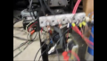
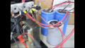
alright check these out. Maybe you guys can figure out what all is going on here.Well I watched the video... So where was the big capacitor, the pi filter, etc?
What he had was a 28v secondary centre tapped, some old cruddy alternator diodes and a 0.9uF capacitor which I'm not even sure was used. As far as I can see he had essentially raw unfiltered DC coming out of that setup which was so inefficient that it dropped to 7v on load from 14v AC rms (20v peak). It was probably wasting as much energy as heat as it was doing electrolysis. He has near 100% ripple!
Attachments
-
 8.5 MB Views: 6
 -
 7.4 MB Views: 5
 -
 8 MB Views: 5
 -
 8.5 MB Views: 5
 -
 8.5 MB Views: 5
 -
 6.9 MB Views: 5
 -
 6.8 MB Views: 5
OK, so you have some pictures of a very messy power supply that would be great for a high power amp but is, IMHO, complete overkill for electrolysis. I know you didn't want a discussion on the subject but given I've invested a couple of hours of my time in this I'm intrigued by your assertion that you need very low ripple? On what do you base that assertion?
"Educational" value aside, you can pick up a 5v 30A PSU on eBay for $30, hell of a lot simpler and safer for you, & better for the environment given their 80%+ efficiency.
I've used my 0 - 60v, 0 - 50A supply (the same one I use for charging my big lithium packs) for anodising and nickel plating in the past. Until I did a bit of YouTube-ing yesterday I hadn't made the connection between those and electrolysis (Doh!).
Last edited:
MisterBill2
- Joined Jan 23, 2018
- 27,639
My comment in post #86 is about some stuff that I have. I was only addressing the remarks about how big and heavy the system would be, not commenting on any items that have been mentioned.
The voltage drop in a filtered system depends on the current and the ability of the capacitor to deliver current during the portion of the cycle when the diodes are not conducting.
I suggest an analysis of the load requirements with the intent of determining the actual voltage regulation and ripple content requirements, because those will have the very large effect on the complexity and cost of the system.
First - how is it there have been so many posts to this thread and I'm not getting notifications?
The best advice (my opinion) is that you use a 14V center tapped configuration giving 7-0-7 output. Seven volts to the center tap and seven volts from the center tap to the other lead. The benefit is that you only need two diodes as opposed to four as a full wave rectifier. And as MisterBill2 said, with a full wave (Bridge Rectifier (BR)) rectifier you're running power through two diodes at all times. Whereas with the center tapped transformer you only go through one diode at a time. You lose half as much as you do with a BR.
I recall dismantling a Weller soldering gun. It consisted of a very large primary with what amounted to a single loop secondary. The current through the soldering tip was what heated it up. Very low voltage with very high (unknown) amperage to produce a working solder tip. I've seen them break down and arc across the break. Small arc, but an arc nonetheless.
I think I speak for everyone here - but wouldn't presume to do so - when I say "If we give you bad advice and you get hurt - the person giving you that advice is responsible." So I don't want to lend bad advice that could contribute to your injury or death. I'd hate to have that on my conscience.
Electroplating? Yeah, that is high current. Higher plates faster. But you mention some sort of production line. Where are you going to get all these scrapped MOT's from? You'd be better served buying the transformers you need. Having worked for Naval Power Systems, I've seen some pretty damned big transformers. Truth is - what you want is out there. Building to a particular application is fine. As long as you keep two things in mind - your safety - and the safety of the end user.
[edit] meant to include this link: https://en.wikipedia.org/wiki/Center_tap
I've done that. Using an angle grinder I've cut through the weld on the core. Just deep enough to allow me to break it open. Once opened I could coax the secondary and the heater wires out without bothering the primary or the choke (the sideways metal pieces - can't recall the name). Having a welder and some experience, I'd position the newly modified MOT in a vise and weld up the EI core to close things back in. Also I didn't damage the paper shields that came out of the MOT and reused them to guard against damage from the core.Some EI cores can be separated and the bobbins removed individually.
First thing I would say about that is "No. Don't do that." We're talking enough heat to possibly reflow the solder, and that could lead to bridging.I was wondering if I could use some solder to fix the knicks in the wire
I've seen LOTS of things done on YouTube. Things I would not recommend trying. No, I didn't watch your video but I DID read @Irving's review of the video. Sounded like what I would have expected. People do things that work. But that's all they do - work. For the moment. There's a LOT of hacks on YouTube. Even I've hacked a few things in the past. One was to use a carbon filter from a reverse osmosis filtration system as a huge resistor. Why? Just because it COULD be done. No practical use for it though. Just because you've seen it done doesn't mean it's the best way to go.I want to reiterate that I have seen this done with my own eyes
Neither do I. The reason why an alternator has six diodes is because an "Alternator" produces AC. And it does so in three phase configuration. That's why an alternator has six diodes. And like @MisterBill2 said, they are very well ventilated. Air cooled.You believe that the alternator diodes are not a great route
The best advice (my opinion) is that you use a 14V center tapped configuration giving 7-0-7 output. Seven volts to the center tap and seven volts from the center tap to the other lead. The benefit is that you only need two diodes as opposed to four as a full wave rectifier. And as MisterBill2 said, with a full wave (Bridge Rectifier (BR)) rectifier you're running power through two diodes at all times. Whereas with the center tapped transformer you only go through one diode at a time. You lose half as much as you do with a BR.
I recall dismantling a Weller soldering gun. It consisted of a very large primary with what amounted to a single loop secondary. The current through the soldering tip was what heated it up. Very low voltage with very high (unknown) amperage to produce a working solder tip. I've seen them break down and arc across the break. Small arc, but an arc nonetheless.
I think I speak for everyone here - but wouldn't presume to do so - when I say "If we give you bad advice and you get hurt - the person giving you that advice is responsible." So I don't want to lend bad advice that could contribute to your injury or death. I'd hate to have that on my conscience.
Electroplating? Yeah, that is high current. Higher plates faster. But you mention some sort of production line. Where are you going to get all these scrapped MOT's from? You'd be better served buying the transformers you need. Having worked for Naval Power Systems, I've seen some pretty damned big transformers. Truth is - what you want is out there. Building to a particular application is fine. As long as you keep two things in mind - your safety - and the safety of the end user.
[edit] meant to include this link: https://en.wikipedia.org/wiki/Center_tap
Maybe you accidentally clicked "Unwatch thread"?First - how is it there have been so many posts to this thread and I'm not getting notifications?
If I get injured it is because I made a mistake. Please read the whole thread, completely. Many people just fire off their own input and have no idea where the conversation has gone. There is no assembly line. I work with 220 all day, every day. If I get hurt it will be at my day job. Wether you tell me, or I read it, I’m going to do it. I may not succeed, but I will try again, until I succeed. I’m in school for electrical engineering and this is a good project to learn from, but this is a hobby. Please don’t read this with any tone. I’m not angry, or telling you off. I am a student not a professional, but I will be a professional with, or without this advice online. I enjoy talking about things with people that are like minded. Many people find me annoying because I talk too much about technical aspects of everything I do. I’m learning as well as enjoying the social aspect of “all about circuits” interactions.First - how is it there have been so many posts to this thread and I'm not getting notifications?
I've done that. Using an angle grinder I've cut through the weld on the core. Just deep enough to allow me to break it open. Once opened I could coax the secondary and the heater wires out without bothering the primary or the choke (the sideways metal pieces - can't recall the name). Having a welder and some experience, I'd position the newly modified MOT in a vise and weld up the EI core to close things back in. Also I didn't damage the paper shields that came out of the MOT and reused them to guard against damage from the core.
First thing I would say about that is "No. Don't do that." We're talking enough heat to possibly reflow the solder, and that could lead to bridging.
I've seen LOTS of things done on YouTube. Things I would not recommend trying. No, I didn't watch your video but I DID read @Irving's review of the video. Sounded like what I would have expected. People do things that work. But that's all they do - work. For the moment. There's a LOT of hacks on YouTube. Even I've hacked a few things in the past. One was to use a carbon filter from a reverse osmosis filtration system as a huge resistor. Why? Just because it COULD be done. No practical use for it though. Just because you've seen it done doesn't mean it's the best way to go.
Neither do I. The reason why an alternator has six diodes is because an "Alternator" produces AC. And it does so in three phase configuration. That's why an alternator has six diodes. And like @MisterBill2 said, they are very well ventilated. Air cooled.
The best advice (my opinion) is that you use a 14V center tapped configuration giving 7-0-7 output. Seven volts to the center tap and seven volts from the center tap to the other lead. The benefit is that you only need two diodes as opposed to four as a full wave rectifier. And as MisterBill2 said, with a full wave (Bridge Rectifier (BR)) rectifier you're running power through two diodes at all times. Whereas with the center tapped transformer you only go through one diode at a time. You lose half as much as you do with a BR.
I recall dismantling a Weller soldering gun. It consisted of a very large primary with what amounted to a single loop secondary. The current through the soldering tip was what heated it up. Very low voltage with very high (unknown) amperage to produce a working solder tip. I've seen them break down and arc across the break. Small arc, but an arc nonetheless.
I think I speak for everyone here - but wouldn't presume to do so - when I say "If we give you bad advice and you get hurt - the person giving you that advice is responsible." So I don't want to lend bad advice that could contribute to your injury or death. I'd hate to have that on my conscience.
Electroplating? Yeah, that is high current. Higher plates faster. But you mention some sort of production line. Where are you going to get all these scrapped MOT's from? You'd be better served buying the transformers you need. Having worked for Naval Power Systems, I've seen some pretty damned big transformers. Truth is - what you want is out there. Building to a particular application is fine. As long as you keep two things in mind - your safety - and the safety of the end user.
[edit] meant to include this link: https://en.wikipedia.org/wiki/Center_tap
To reiterate, I’m scared of these transformers. I respect them, while I may not know as much as anyone here, I understand what an arc is. I understand how I could get hurt and how. I don’t think anyone in their right mind pulls a microwave apart, takes the transformer out, and plugs it into an outlet with no concept of the danger involved. I appreciate your concern but, I am an adult and am responsible for my own safety. Your help is appreciated and will help me remain much safer because, it will be done right.
please remember I am not angry. I mean no disrespect! Context and social acuity mean the world in online exchanges.
I base that assertion from experience. The YouTube video was not where I initially started. I had an acquaintance show me there power supply and success. I do not speak with said acquaintance anymore.OK, so you have some pictures of a very messy power supply that would be great for a high power amp but is, IMHO, complete overkill for electrolysis. I know you didn't want a discussion on the subject but given I've invested a couple of hours of my time in this I'm intrigued by your assertion that you need very low ripple? On what do you base that assertion?
"Educational" value aside, you can pick up a 5v 30A PSU on eBay for $30, hell of a lot simpler and safer for you, & better for the environment given their 80%+ efficiency.
I've used my 0 - 60v, 0 - 50A supply (the same one I use for charging my big lithium packs) for anodising and nickel plating in the past. Until I did a bit of YouTube-ing yesterday I hadn't made the connection between those and electrolysis (Doh!).
Experience shows that when there is high ripple anodes and cathodes are absolutely destroyed in a fraction of the time. Depending on what the end goal is, some anodes can be extremely expensive. I am going the MOT route because I believed it was a good way to learn about all the aspect we are trying to cover, as well as accomplishing the power demand with low ripple. It does not have to be 25 amps, that is what the Aformentioned acquaintance sad because it shortened run times as well as allowed for more possibilities.
Now that we have those responses out of the way, I’m lost. I have one transformer with a my own 10 gauge trial winding putting out close to 12 volts. I need to remove this and wind 1 seven volt winding, then another seven volt winding. Then comes working on a full bridge rectifier, once this is done I still need a filter and diodes, correct?
First thing I checked. No - I'm still watching this thread. Part of the reason for this comment is that there have been so many more posts since I last commented.Maybe you accidentally clicked "Unwatch thread"?
I have done that. I thought I read that somewhere someone mentioned a production line. If I'm in error - oops. That happens.Please read the whole thread, completely.
The whole point about warning is because, well, at least me myself, I don't want to be responsible for bad advice that leads to someone's injury. Sort of a cover my own behind. At the same time it's meant to protect others who read this thread. And face it, a lot more people may research this topic and see what you're doing and think of a different way to accomplish something similar. Without warnings - they might make a fatal mistake. None of us think you're incompetent. We just realize the potential for injury when handling 120 VAC. HERE is a post I just posted as a finished product. I suspect a moderator may move it to an appropriate location, but for now - and it doesn't necessarily apply to your project.
Not exactly. If you're going with a center tap you'll only need two diodes capable of handling the wattage that will pass through them. If you go with a full wave BR you won't need a center tapped transformer. Engineering choices are up to you as to how you want to proceed. Did you have a look at the link I posted on center tapped transformers? If not - it may be useful. May not be necessary if you already know what a center tap is. Just covering all bases.Now that we have those responses out of the way, I’m lost. I have one transformer with a my own 10 gauge trial winding putting out close to 12 volts. I need to remove this and wind 1 seven volt winding, then another seven volt winding. Then comes working on a full bridge rectifier, once this is done I still need a filter and diodes, correct?
As for filters - again, that's an engineers choice. Heed the advice you've gotten so far. I'm no engineer. But it would be of concern to get the appropriate choke (coil) for your filter as well as capacitors that can handle the loads AND a robust transformer that can handle the load the caps will put on it at startup. {see - I did read the entire post}
Well that’s partially the problem. I’m Just finishing calculus up. I guess I can’t call myself an engineer yet. The setup I saw was the two transformers with two modified windings outputting 14 volts. It had two large capacitors setup as pi filters, and the alternator diodes. Everyone has made their suggestions, and then someone warns against every suggestions, as well as mine. I guess I will just have to give pick one and try it after ample research. The only I have down solid from posting is that the way I thought this would work is completely wrong and I shouldn’t do it the way I was going to try.Not exactly. If you're going with a center tap you'll only need two diodes capable of handling the wattage that will pass through them. If you go with a full wave BR you won't need a center tapped transformer. Engineering choices are up to you as to how you want to proceed. Did you have a look at the link I posted on center tapped transformers? If not - it may be useful. May not be necessary if you already know what a center tap is. Just covering all bases.
As for filters - again, that's an engineers choice. Heed the advice you've gotten so far. I'm no engineer. But it would be of concern to get the appropriate choke (coil) for your filter as well as capacitors that can handle the loads AND a robust transformer that can handle the load the caps will put on it at startup. {see - I did read the entire post}
In my project with the control panel I didn't use a transformer. Just line voltage applied to the control panel and to the HOT outlet. The panel controls the Switched outlet.What was the reason for using the transformer and microwave panel?
As far as your possible confusion about full wave rectification methods, here are two: The upper transformer has an output voltage that is Bridge Rectified (four diodes in a housing). At all times current is passing through two diodes regardless of the AC wave. The lower is a center tapped transformer that also is full wave rectified, but not using a BR. Both transformers operate the same way but with the lower you're only passing through one diode at a time. That's important because a diode will have a typical voltage drop of about 0.7 volts. Running through one diode at a time will only drop 0.7 volts whereas with a full wave BR you're dropping 1.4 volts (0.7 x 2).


