Facebook
 Google
 GitHub
 Linkedin
I have only done research and modified transformers to measure outputs of primary windings. I know what size gauge to use and how many turns to yield the desired output on the secondary. I’m not concerned about figuring out the math and variables involved, if that’s what your asking? I will gladly accept your input on the matter.
[/QUOTE
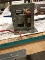
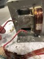
MOT power supply
- Thread starter Hutch2793
- Start date