More linear amplification

Thread Starter

PatrickMalarkey

Joined Oct 2, 2021
120
FM broadcast music, USA FCC range is 88 Mhz. to 108 Mhz. Stereo, and today more than what's called a one channel. Actual frequencies for music probably haven't changed, but lots more broadcast these days with music.
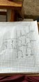
My intent is to test "resistive" biasing of a bipolar amplification system, and I bought an old Realistic Tuner for it's variable tuning capacitor and coil for tuning an RF. And yes I was serious with my "conclusion to an unfinished matter" post and omitting coupling and bypass capacitors. All stabilization is to be done with resistors, WITHOUT capacitors, but sorry I don't have the terminology to explain why.
To kick it harder there's a much better way to test a bipolar amplification system than with a broadcast signal. That's to use the Digital-to-Analog Converter in my phone and route the audio to a homemade amp. using that "resistive" coupling. And please don't ask me why I didn't think of that in the beginning. Because I don't really know if I'm ever going to try building up a discrete tuning and preamp circuit, especially the troubleshooting of one. I'll probably buy an old Realistic amp second hand, and put together an audio amp. And use my phone as the source for music, and test it with my ears. That's my testing method, outside of a good, clean, simple design.
 

Thread Starter

PatrickMalarkey

Joined Oct 2, 2021
120
And IanO, your just about to awaken for the day, so I'll be looking for your reply to my question, what's the part number for that FET with a ~ flat 2mA drain current @ -.8 V Vgs. And thank you for sharing the biasing method, I wasn't aware of how to set-up negative feedback. David, not Patrick
 

ericgibbs

Joined Jan 29, 2010
18,766
Why did you tell Ian to hang up at this end?
Hi P,
OT...
I said to Ian, 'in colloquial English' No hang up at this end

Which means the problem you were having with your Conversation, was not due to Moderation, but most likely something you had done, when Creating the Conversation.

E
 

Thread Starter

PatrickMalarkey

Joined Oct 2, 2021
120
Hi P,
OT...
I said to Ian, 'in colloquial English' No hang up at this end

Which means the problem you were having with your Conversation, was not due to Moderation, but most likely something you had done, when Creating the Conversation.

E
Correct Eric, I used the wrong option to privatize my message to IanO. Also, I might add that I found it difficult to see how to send my message after I'd written it. I did evidently use the correct option: START CONVERSATION.
 

Thread Starter

PatrickMalarkey

Joined Oct 2, 2021
120
This is how things stand View attachment 259267with that tuner/pre-amp
Is the "I" a lower case "L"?
Is Ian0 still available for comment as he has been doing? He seems to be an audio engineer or technician experienced with the stage my "Whatever you want to call it" is currently focused. That stage is now focused on a discrete-component audio amp with "resistive coupling/stabilization" in it's biasing. I can probably explain that to him better than a moderator, except for my overall intent, or purpose. My efforts aren't for doing anything with past musical recording, but the future of digital recording and associated amplification. I mostly want to preserve the original integrity of "acoustical instrument produced" music for the Listener's enjoyment (as I would prefer). And this is my contribution towards that goal. I hope to make a general suggestion-disclosure to the Lockheed/Martin Corp. for their review in any division's interest they might have.
 

Ian0

Joined Aug 7, 2020
9,679
And IanO, your just about to awaken for the day, so I'll be looking for your reply to my question, what's the part number for that FET with a ~ flat 2mA drain current @ -.8 V Vgs. And thank you for sharing the biasing method, I wasn't aware of how to set-up negative feedback. David, not Patrick
That is a Toshiba 2SK208. The Japanese make quite a few nice JFETs for Audio. Some of them you will find at OnSemi, because they bought them from Sanyo (or was it Sanken).
 

Thread Starter

PatrickMalarkey

Joined Oct 2, 2021
120
That is a Toshiba 2SK208. The Japanese make quite a few nice JFETs for Audio. Some of them you will find at OnSemi, because they bought them from Sanyo (or was it Sanken).
Ian0, I thought I'd post this photo of a class C power amp, that uses resistors only, for biasing a bipolar amp. system. It is expected to avoid the distorted musical waveform caused by capacitor charging rates. (time constant governed charging and discharging rates as discussed in basic AC theory entry level education). The musical "note" consists of a "slowly decreasing frequency" with a "diminishing intensity or volumn", and is slightly distorted by maximum charging and discharging rates of reactive devices and their associated "time-constant", governing the rate at which they pass current. Included is a sketch of that amplifier with it's biasing resistors. It is balanced for an AC operating Q with a gain of 2.IMG_20220205_060053238_HDR~2.jpg
 

Thread Starter

PatrickMalarkey

Joined Oct 2, 2021
120
Ian0, I thought I'd post this photo of a class C power amp, that uses resistors only, for biasing a bipolar amp. system. It is expected to avoid the distorted musical waveform caused by capacitor charging rates. (time constant governed charging and discharging rates as discussed in basic AC theory entry level education). The musical "note" consists of a "slowly decreasing frequency" with a "diminishing intensity or volumn", and is slightly distorted by maximum charging and discharging rates of reactive devices and their associated "time-constant", governing the rate at which they pass current. Included is a sketch of that amplifier with it's biasing resistors. It is balanced for an AC operating Q with a gain of 2.View attachment 259732
And Ian0, the next photo is the preamp stage for the last sketch. It shows the tone controls for bass and treble as shunt reactive devices which allow unwanted attributes to get trapped between the two reactive branches. But most importantly the musical note attributes pass to the amplifier stages. Only one channel of stereo amplification is shown.IMG_20220205_222153396_HDR~2.jpg
 

Attachments

Thread Starter

PatrickMalarkey

Joined Oct 2, 2021
120
It would make things easier to understand if you identified which terminal is collector and which is emitter on your transistors.
Alright, I'll do that very thing, today. With any reasonable amount of time, the two drawings should be posted later today. Their emitters will carry the arrowhead for convention flow, collectors should be identified by the Vcc+ label, output lead in a common emitter location and base lead midway to the "spine" of the symbol. I don't know if you mean the drawing of the tone control and preamp or just the power amp, but I'll try to get both drawings re-done. (something I'll need to do first, in addition to drafting a disclosure for Lockheed/Martin)
 

Thread Starter

PatrickMalarkey

Joined Oct 2, 2021
120
Alright, I'll do that very thing, today. With any reasonable amount of time, the two drawings should be posted later today. Their emitters will carry the arrowhead for convention flow, collectors should be identified by the Vcc+ label, output lead in a common emitter location and base lead midway to the "spine" of the symbol. I don't know if you mean the drawing of the tone control and preamp or just the power amp, but I'll try to get both drawings re-done. (something I'll need to do first, in addition to drafting a disclosure for Lockheed/Martin)
Ian0, here's the first drawing of a power amp. The second drawing is something I'll haf to start over with. But I expect to be finished by tonight, Sunday.IMG_20220206_075203347_HDR~3.jpg
 

Audioguru again

Joined Oct 21, 2019
6,674
A "class-C" circuit conducts for only part of the waveform. Your transistor circuit is a "class-A" room heater that amplifies a bit but with distortion because transistors are not linear and your circuit has only a little amount of negative feedback. Most audio amplifiers use class-AB for low heating with no signal.

The input coupling capacitor is important because it blocks the 0VDC from the signal source.
The output coupling capacitor is important because it blocks DC in the speaker from damaging it.

The transistor is distorted (the bottom of the waveform is squashed a little) because it is not linear.

I simulated your circuit but it needed an important input coupling capacitor so that the input biasing works.
The speaker R6 needed a coupling capacitor to prevent DC from damaging it.
The biasing resistor R2 needed to be reduced to match the beta of my transistor.
There is no voltage gain, 10V peak input gives 7V peak output.

Then the output power is only 3.1W but the heating power of the parts is 62.3W!
A class-AB amplifier (LM3886 for example) will have very low distortion and an output of 20W into 8 ohms with this 40V power supply.
 

Attachments

Thread Starter

PatrickMalarkey

Joined Oct 2, 2021
120
A "class-C" circuit conducts for only part of the waveform. Your transistor circuit is a "class-A" room heater that amplifies a bit but with distortion because transistors are not linear and your circuit has only a little amount of negative feedback. Most audio amplifiers use class-AB for low heating with no signal.

The input coupling capacitor is important because it blocks the 0VDC from the signal source.
The output coupling capacitor is important because it blocks DC in the speaker from damaging it.

The transistor is distorted (the bottom of the waveform is squashed a little) because it is not linear.

I simulated your circuit but it needed an important input coupling capacitor so that the input biasing works.
The speaker R6 needed a coupling capacitor to prevent DC from damaging it.
The biasing resistor R2 needed to be reduced to match the beta of my transistor.
There is no voltage gain, 10V peak input gives 7V peak output.

Then the output power is only 3.1W but the heating power of the parts is 62.3W!
A class-AB amplifier (LM3886 for example) will have very low distortion and an output of 20W into 8 ohms with this 40V power supply.
Those are bipolar transistors, not FET's Audioguru. And I don't know how you've gotten your figures. BETA DC denotes the ratio of base current to collector current in a bipolar amp., it's not a matter of transconductance. I've abandoned the attempt to get linear amp. from an inherently non-linear device. As it is an "understanding" of mine that the qualities of acoustical notes can be preserved by replacing all coupling and bypass capacitors with resistors. What is the date of the post I've evidently made, because today's post isn't of an FET amplifier system
 

Thread Starter

PatrickMalarkey

Joined Oct 2, 2021
120
Ian0, here's the first drawing of a power amp. The second drawing is something I'll haf to start over with. But I expect to be finished by tonight, Sunday.View attachment 259847
Ian0, this is the #2 photo. Adding actual circuit values are next, but that will be done later today. And another post will follow with those values.
Ian0, here's the first drawing of a power amp. The second drawing is something I'll haf to start over with. But I expect to be finished by tonight, Sunday.View attachment 259847
IMG_20220206_125303664_HDR~4.jpg
Ian0, here's the first drawing of a power amp. The second drawing is something I'll haf to start over with. But I expect to be finished by tonight, Sunday.View attachment 259847
Ian0, here's that #2 sketch, next is assigning actual values to the elemfnts
Ian0, here's the first drawing of a power amp. The second drawing is something I'll haf to start over with. But I expect to be finished by tonight, Sunday.View attachment 259847
IMG_20220206_125303664_HDR~4.jpgThis is the tone control and preamp for that Class "C" power amp. Note the shunt circuit with two reactive devices acting to "trap", and "hold" unwanted base or treble frequencies. This shunt arrangement removes a portion of the musical note, but not the "critical" part of the integrity of an acousticalIMG_20220206_075203347_HDR~3.jpgIMG_20220206_125303664_HDR~4.jpg instrument.
Ian0, here's the first drawing of a power amp. The second drawing is something I'll haf to start over with. But I expect to be finished by tonight, Sunday.View attachment 259847
Ian0 as you might have guessed it's going to take me a while to review low frequency bipolar transistor amps before any values are placed on the components of my most recent post. today.
 

Audioguru again

Joined Oct 21, 2019
6,674
Almost all low distortion audio amplifiers use bipolar transistors in a class-AB complementary push-pull circuit and input and output coupling capacitors. Most have very low distortion that cannot be heard.
A ceramic coupling capacitor adds distortion because its capacitance changes with the signal voltage, and they are microphonic.
Film capacitors cause no distortion. A resistor cannot replace an important capacitor.

I have seen many hifi amplifier circuits but I have never seen one with FETs.
But I have used audio opamps that have FET inputs.

You did not like my figures? Here is your original class-A transistor power amplifier circuit with an important input coupling capacitor added. It has idle heating of 81.5W and a max output before clipping of only 0.138W. Terrible efficiency!
 

Attachments

Audioguru again

Joined Oct 21, 2019
6,674
All tone controls boost and cut bass and treble but yours only cut.
Now I see that you are bridging two class-A amplifiers for more output power plus a lot more heating power.
Many bridged modern amplifiers use class-D switching for very high efficiency even when playing a high output power.

Instead of class-A outputs you should use class-AB.
 

BobTPH

Joined Jun 5, 2013
8,814
You are about to have an epiphany, but only if you take the time to read and understand what I am saying.

You assert that the long charging times of coupling capacitors distorts the waveform being amplified. So lets take that to a reducto ad absurdum. Lets make the input coupling capacitor very large, 1000 uF coupling an input with an impedance of 10000 Ohms. RC = 10 seconds.

This ought to make for horrible distortion according to your theory, right?

So, lets feed it a 1000Hz signal. With a time constant of 10 seconds, it is not going to charge by any significant amount in the positive half cycle of 500 usec, is it?

Since there is essentially no charging, the voltage across the capacitor does not change, and so the amp side if the capacitor rises and falls in exactly the same way as the input side. In other words, no distortion.

Now make that capacitor very small. Say 1 pf for an RC constant of 10 usec. This time, the half cycle is 50 time constants, which means the capacitor fully charges during a half cycle. And see the difference between the input side and the output side pretty much tracks the input signal meaning there is no change on the amp side, essentially none of input signal gets through! Serious distortion!

So you have it backwards, long charging times do not create distortion, short ones do.

So what do designers do to avoid the distortion? They make the coupling capacitors large enough for the frequencies if interest.

Or I coukd have said all that in a simpler way: A coupling capacitor and the impedance it is driving make a high pass filter, and if we design its cutoff frequency to be well below the desired frequency range, it does not introduce significant distortion.

Bob
 
Top