monostable 555 trouble

Thread Starter

toolmanx

Joined Dec 3, 2013
10
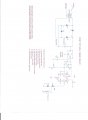
I built a timer to watch the time my well power is on. It should shut off the power if it runs longer than one minute. It works but the self latching relay in the pin 3 circuit trips if the power goes off too close to the set time. I've noticed a positive pulse that occurs on pin 3 when this happens. If you need a schematic of my total circuit, let me know how to post it. I have it in old MIcroCap. I've found that people that have new MC lose the sizes when importing mine. I can also scan a pic of the circuit in if the site will accept it.
If you want to chat with me directly, use my e-mail address.
 

Thread Starter

toolmanx

Joined Dec 3, 2013
10
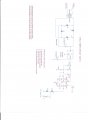
I have built 2 versions of this timer. Both fail at power on or off times. Your site indicates I need these drawings on the internet to post them. Give me instructions on how to set this up. I have scanned the drawings ready to send them.
 

MikeML

Joined Oct 2, 2009
5,444
Post Reply or Quick Reply, followed by Go Advanced.

Down the page, look for Manage Attachments. Click on that

Click on Browse, and locate the file you want to upload on your hard drive.

Then Upload, followed by Close Window after finished uploading.

Finally, Submit Reply.
 

Thread Starter

toolmanx

Joined Dec 3, 2013
10
The second try circuit is now history. It tripped the relay on turn on. Totally worthless.

I have now removed the separate trigger circuit because it wasn't triggering and put the circuit back to when it was working but opening the relay on turn off. I now have a 1 meg timing resistor in series with two 22ufd caps in parallel with the caps from B+ to the resistor. I made a chart of the voltage versus time and when the relay latches up on turn off.

Trig Volts Time

10V 15sec No trip if turned off
9V 20sec Start of trip out on off
8V 25sec “
7V 30sec “
5.5V 45sec Timed out and trips as it should
 

Dodgydave

Joined Jun 22, 2012
11,395
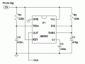
You need a monostable cct like this, if you want the circuit to trigger on power up, then replace the trigger button with a 1uF capacitor, the delay is set by the values of R and C
 

Thread Starter

toolmanx

Joined Dec 3, 2013
10
Well I surrendered this morning. I had put the threshold from floating, to B+, to ground where it is now. Nothing helped. When the trigger voltage gets below 7V the relay trips on a power off because the 555 changes state momentarily. I added one more 22ufd cap in parallel to increase the time. The time out occurs now at my old set point of 1 minute 15 seconds. I get into the danger zone of 7V trigger voltage at 45 seconds. With my wife watering her garden with a hose, the well refills in 40 seconds. That’s cutting it close.

So as I said, I surrendered. I put the timer back into the well house, removed all the jumpers and wired in the box. I’m not happy but I’ve run out of ideas.

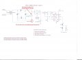
The latest pic is the circuit as it is now. It works unless it is on too long.
 

Thread Starter

toolmanx

Joined Dec 3, 2013
10
To answer your questions. Yes that ground is there. I have rebuilt many iterations of this circuit to test. I started with a 1000 ufd filter cap. I changed because I felt the B+ might be holding too long. Neither way worked. I looked over Dodgydaves circuit. It misses the point. I don't have a button to trigger. I start the timing on power up and pull in a relay if it times out. The problem is when the trigger voltage gets around 7V or lower as it is going down, the 555 changes state if the power is turned off. Even though there is no applied power, the declining B+ pulls in the relay. I can see this change of state jumping up positive on my scope.
 

Alec_t

Joined Sep 17, 2013
15,133
Try re-configuring the 555 like this. R1/C2 delay the trigger voltage with respect to the V+, thus keeping the trig voltage above V+ as V+ declines :-

Edit: A 1k or so resistor between the discharge pin and the cap should be added to limit discharge current.
 

Attachments

Thread Starter

toolmanx

Joined Dec 3, 2013
10
I've tried so many different ways to do this. I can't use any circuit that ties the cap to ground and the resistor to B+. The 555 change of state at start up is just slow enough that the relay trips on power on. Of course, the relay has to be set up to fire on a low when the cap is tied to ground. That configuration was so lousy, I tossed out all attempts using that. Can your idea be changed to work with the timer components reversed?
 

MrChips

Joined Oct 2, 2009
34,981
There are more than one ways to skin a cat.

I'm not sure what you are attempting to do but trying to get accurate timing at long time constants is not the easiest thing for a 555 timer.

One solution is to run the 555 timer at a higher clock frequency and use counters to set the time delay. After you have done that you can easily fix the power on/off glitches.

Edit: You can also get what you want with a single 8-pin MCU, no external timing components required.
 
Last edited:

Thread Starter

toolmanx

Joined Dec 3, 2013
10
I'll try to answer two questions. First, I have a note on the drawing that explains how the relay works and that there are contacts not shown and a large contactor not shown that actually switches the pump on.

Second, all builds of this circuit that I put together failed at power off or on. When the cap is tied to B+, the pin 3 starts out low and trips to high. It probably gets a short high bump as the power is coming up but not enough to trip the relay. However when the cap is grounded, the 555 starts out with a quick low before settling high. Since the relay needs B+ on it from the get go or it will trip, the momentary low trips it out at power turn on.
 

Alec_t

Joined Sep 17, 2013
15,133
However when the cap is grounded, the 555 starts out with a quick low before settling high.
Surely that's what you want? I was under the impression you wanted the pump to turn on at power-up. A 'quick low' (fraction of a second delay) seems inconsequential.
Since the relay needs B+ on it from the get go or it will trip, the momentary low trips it out at power turn on.
With the conventional circuit I posted the relay is energised a fraction of a second (allowing the power supply to stabilise) after power-up and remains energised for ~1 min.
 
Top