Monitor 24V smoke sensor with PICs ADC

Thread Starter

LewisMF

Joined Nov 15, 2014
119
I looked up the installation manual on some similar sensors (since Lewis hasn't provided the model number that he intends to use). The "end of line" resistor that he talks about is actually connected in parallel with all the sensors. I think it is a method of making sure that the bus has not gone open...

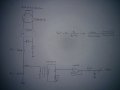
Here is my best guess as to what is going on showing both the EOL resistor R1 and a sensing resistor R2

View attachment 81146

The 24V supply is actually inside the Alarm Panel. It likely is wired in series with a sensing resistor R2 (as I surmised way back in my first post), which serves both to limit the current from the power supply, as well as to provide a voltage proportional to the total current being drawn by the sum of the EOL resistor and the sensors.

To protect the A/D input, I have added a series resistor R3 and a 4.7V Zener diode, which will allow measuring the difference between the just the EOL resistor with no alarms, and the first and subsequent alarms. If multiple sensors alarm, the Zener limits the voltage into the A/D.

Now we just need to agree on R1 and R2...
Hi MikeML,

In post #5 I posted the datasheet of the sensor (page 7), even know these alarm panels are designed to work with all kind of conventional smoke sensors like these.

The schematic you posted looks great. I like the idea of sensing on the negative wire, but how would this be done as the voltage will always be 0V ??

Another thing, what protection would this circuit have against short circuits?
 

ErnieM

Joined Apr 24, 2011
8,415
Mike's sense is ground referenced across R2. It is not grounded.

I mentioned short circuit protection: add a resistor in the + outgoing leg. R2 alone may do it but I didn't run those numbers.
 

Thread Starter

LewisMF

Joined Nov 15, 2014
119
Mike's sense is ground referenced across R2. It is not grounded.

I mentioned short circuit protection: add a resistor in the + outgoing leg. R2 alone may do it but I didn't run those numbers.
Thanks Ernie, I did not realize this.

Thank you guys for your help.
 

Thread Starter

LewisMF

Joined Nov 15, 2014
119
Well guys I have run the numbers for R1 = 5.1 Kohm, R2 = 100 ohm & Rsensor = 600 ohm (only when sensor is in alarm) and these are the results:

For normal condition (No sensors alarming) the voltage before the resistor to the ADC would be:

Vout = Vin * (R2/R2+R1) = 24 * (100/100+5100) = 0.46V = 460mV

For alarm condition (One sensor in alarm) the voltage before the resistor to the ADC would be:

Rp = (R1*Rsensor) / (R1+Rsensor) = 536.84 ohm

Vout = Vin * (R2/R2+R1) = 24 * (100/100+536.84) = 3.76V

---------------------------------------------------------------------------------------------------------------------------------------------------------
For more detectors in alarm the voltage before the resistor to the ADC would be considerably higher. 4.7V will drop across the Z diode and the rest would drop across the 4.7K resistor and the sense resistor. The only doubt I have is if the uC will get damaged. What do you think?

If all 32 detectors are alarming, something that is practically impossible, what would happen? I need to make sure nothing gets damaged, any ideas?

In normal condition (No detectors in alarm) how could I sense the end of line resistor 5.1 Kohm being removed?
 

ErnieM

Joined Apr 24, 2011
8,415
The resistor and zener will keep the input safe for all conditions. So would a diode to the 5V.

If the end of line resistor goes away (indicating an open) what you call "Vout" goes to zero.

Have you considered what Vout does when the line shorts?
 

Thread Starter

LewisMF

Joined Nov 15, 2014
119
The resistor and zener will keep the input safe for all conditions. So would a diode to the 5V.

If the end of line resistor goes away (indicating an open) what you call "Vout" goes to zero.

Have you considered what Vout does when the line shorts?
What do you mean by "a diode to the 5V" ?

I thought that maybe a standard 1N4001 diode across +24 and GND would do it, what do you suggest? I haven´t really thought about this matter.

The real problem I think is if all 32 sensors are alarming at the same time, which like I said before is something very rare, the current would be aproximately 1.28A!! I think the control circuitry needs some protection against that, specially R1 and R2.

I would like to thank you once again for your help.


ErnieM

Joined Apr 24, 2011
8,415
Assuming you are using Mike's schematic...

All sensor firing is expected during a major fire event, but then I would expect the warning system to burn up with the rest of the stuff. However, a shorted line is an expected event you should protect against.

R1 is shorted by the short so it just needs to handle the nominal voltage (24V?).

R2 should be sized so it can take the full 24V. For a 100 ohm resistor and 24V I would use 10 watts minimum.

The diode is there to protect the sense input pin. A 1N4001 can handle the current but may have an excessive drop so look at a schottky type. Or just use the zener, that's probably cheaper at these current levels.
 

Thread Starter

LewisMF

Joined Nov 15, 2014
119
Assuming you are using Mike's schematic...

All sensor firing is expected during a major fire event, but then I would expect the warning system to burn up with the rest of the stuff. However, a shorted line is an expected event you should protect against.

R1 is shorted by the short so it just needs to handle the nominal voltage (24V?).

R2 should be sized so it can take the full 24V. For a 100 ohm resistor and 24V I would use 10 watts minimum.

The diode is there to protect the sense input pin. A 1N4001 can handle the current but may have an excessive drop so look at a schottky type. Or just use the zener, that's probably cheaper at these current levels.

I am using Mikes schematic for the moment.

Yes 10W would be the best option for R2 but al comercial conventional fire alarm panels use excusively SMD components, they use no power resistors at all. I really don´t understand how they do it without using these kind of components. They must use some other kind of circuitry, what do you think?

I think the best option is to use the 4.7V zener diode to keep the input safe, just like Mike used in the circuit.
 

ErnieM

Joined Apr 24, 2011
8,415
Bourns makes a 100 ohm 10W SMD resistor under part number CHF2010CNP101RX. It would require heat sinking built into the PCB.

However, since the single trip current is under 50 mA it would probably be simpler & cheaper to just use a current limited supply for the source.
 

Thread Starter

LewisMF

Joined Nov 15, 2014
119
Hey Guys,

Thinking things over a bit I came up with the following schematic:


I used the HCF4051 IC to be able to monitor up to 8 zones of detectors without using up precious ADC pins on the microcontroller, is this a good solution?

Please let me know what you think about it and correct me if there is any mistakes or easier ways to do it.
 

Attachments

ErnieM

Joined Apr 24, 2011
8,415
I think that misses the point of the single cable.

Now you need 32 cables to protect 32 zones, instead of one cable tapped 32 times.

You only need one A2D for this.
 

Thread Starter

LewisMF

Joined Nov 15, 2014
119
I think that misses the point of the single cable.

Now you need 32 cables to protect 32 zones, instead of one cable tapped 32 times.

You only need one A2D for this.
No because the 32 detectors will be wired in parallel one after another, in the schematic I only showed one. But there will be 32 detectors on the single zone with the end of line resistor on the last one to be able to monitor the whole line.

This way I can have up to 8 zones with 32 detectors on each zone using one single ADC continuously reading each line for a certain amount of time very quickly one after another. So if one zone is alarming it will activate maybe a sounder through a relay or mosfet.

What do you think?

The problem that is still killing me is the current through each zone...
 

ErnieM

Joined Apr 24, 2011
8,415
OK, now I got where you are comming from. The idea should work, though your schematic doesn't quite capture what is needed.

If I get some spare time tonight I'll sketch something up that adds current limiting to the driver section (not just a "pure" voltage power source).

Still going to need to tell which zone is faulting, for line shorts if nothing else.
 

Thread Starter

LewisMF

Joined Nov 15, 2014
119
OK, now I got where you are comming from. The idea should work, though your schematic doesn't quite capture what is needed.

If I get some spare time tonight I'll sketch something up that adds current limiting to the driver section (not just a "pure" voltage power source).

Still going to need to tell which zone is faulting, for line shorts if nothing else.
Hi Ernie,

That would be brilliant. I´ll be waiting for your schematic.

Thanks for your help! :)
 

ErnieM

Joined Apr 24, 2011
8,415
My sketcher is lazy this weekend. Besides, Mike's sketch really covers all the main points.

I'd drive this off something like say a 78L24 regulator, which limits the current to .1-.15 amps. You could even use that over multiple lines.

If you drop R2 even lower to 25 ohms you still get good resolution but a lower power resistor. Nominal voltages are:

Open 0 V
Trip (single) 1.1V
Shorted 5V

Your A2D should be able to pull these apart.

To switch a chain use the entire chain as presented as the input to the '4051. The LM258 does more harm than good so take it out. The RC is OK, may take some noise of of the readings.

Don't make a decision based on a single reading. Do averaging so you have a definite trend and not a single noise blip.
 

Thread Starter

LewisMF

Joined Nov 15, 2014
119
My sketcher is lazy this weekend. Besides, Mike's sketch really covers all the main points.

I'd drive this off something like say a 78L24 regulator, which limits the current to .1-.15 amps. You could even use that over multiple lines.

If you drop R2 even lower to 25 ohms you still get good resolution but a lower power resistor. Nominal voltages are:

Open 0 V
Trip (single) 1.1V
Shorted 5V

Your A2D should be able to pull these apart.

To switch a chain use the entire chain as presented as the input to the '4051. The LM258 does more harm than good so take it out. The RC is OK, may take some noise of of the readings.

Don't make a decision based on a single reading. Do averaging so you have a definite trend and not a single noise blip.
Hi Ernie,

Just tested this circuit and when the smoke sensor goes in to alarm (passes from 0 ohms to 600 Ohm) the voltage coming out of the voltage divider doesn´t change at all, what do you think about this?

Any other suggestions?

Thanks for your help!
 

ErnieM

Joined Apr 24, 2011
8,415
I would first say send me a drawing of what exactly you mean by "this circuit" then we can all make suggestions.
 

ErnieM

Joined Apr 24, 2011
8,415
OK, *that* schematic. With the sense and the sensor in parallel with the 24V source no wonder there is no change when the sensor fires.
 
Top