module to detect state of the PWM switch

sghioto

Joined Dec 31, 2017
8,729
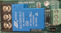
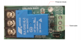
That relay modules has other components on the input coil side of the relay. You will need to trace out the schematic of the input side of the board. We just need to get to the ends of the relay coil. I think there is a diode on the module so we need to know how it is wired.
Les.
None of that is necessary. A diode is installed across the relay coil and the input uses an optocoupler to provide either a High or Low input signal to activate.
 

LesJones

Joined Jan 8, 2017
4,509
It is easier for you to trace out the schematic of the board with it in front of you than it is for us to do it from pictures.
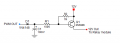
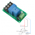
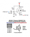
If I am guessing corectly that the boad is designed to be supplied with 12 volts and the jumper pins change the sense of the input signal that activates the relay then connect the negative input to the negative of your power supply and the positive input to the drain of Q1 mosfet. You will need to select the jumprer position that activates the relay coil when the PWM signal is present. Do not connect anyting to the terminal on the module that is designed to be the input signal.
 

sghioto

Joined Dec 31, 2017
8,729
Both work the same, no advantage other then the number of parts used.
There are other options depending on the components you have on hand.
 

Thread Starter

thor21

Joined Sep 29, 2024
435
You will need to select the jumprer position that activates the relay coil when the PWM signal is present.
yes i need to switch jumper to H ie react on 12V on the input CH1

Do not connect anyting to the terminal on the module that is designed to be the input signal.
@LesJones But i dont get that one ... why do not conect anything to that terminal ie CH1?
I though there should be connected port from the @sghioto design ie. 12V Out To relay module?
 

BobTPH

Joined Jun 5, 2013
11,601
@sghioto hi,
regarding the capacitor is it nF or uF? as nano F doestn have poles? thanks!
It is nanoFarad, as it says. There are polarized and non-polarized capacitors in both 100nF and 100uF. Depends on the capacitor you pick. If it is polarized, connect it the way shown.
 

Thread Starter

thor21

Joined Sep 29, 2024
435
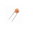
i have the one on the photo ... .can i use that one

1731001624993.png

or do i have to buy polarized 0.1uF ? thanks
 
Last edited by a moderator:

Thread Starter

thor21

Joined Sep 29, 2024
435
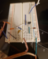
okay so i connected it all,
and even the pwm switch is off; the relay is automatically ON.

and even i turn on pwn switch it does nothing relay is still on.

any idea?


Also i connected together Neg on capacitor + neg on relay + neg on PSU together.

1731003621388.png
 
Top