Facebook
 Google
 GitHub
 Linkedin
I've done some analog electronics, and I've done some model rocketry (basic Estes stuff) however I wanted to take the next step and build my own controller to support Boy Scout and School rocketry. I am thinking of going for 10 launch pads. Without practical knowledge, I am wondering about a few things - especially power supplies. Seems like it would be extremely convenient now days to use one or more tool batteries (such as Dewalt, Ryobi, etc) as these are compact, recharge quickly, easily swap-able, light weight, and can even be charged remotely using a car cigarette lighter accessory. I can hack an old tool from a garage sale to create a "snap in" socket for the battery type. A person could carry four or so batteries and and keep them on a rotating charge if they didn't last the full length of a day of rocketry. Question, could you get enough amps out of them to fire igniters?
Second issue, I have seen numerous designs out there and many seem to suggest using 12 v 30 amp auto relays in the firing circuit (others digital versions but still basically a relay) triggered by a momentary push button for a "Fire" command. I have also seen many that simply use a simple firing path involving an analog switch such as a momentary press plunger without any relay. What are the advantages of using a relay? Are they mostly for larger rocket types, higher amperage, or is there a reason to use a relay in basic rocketry?
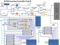
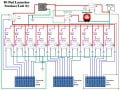
My main idea is to use a simple 12v to USB converter to power all the logic indications and to conduct continuity checks on installed igniters, and have a separate 12v circuit for firing voltage/amperage. As others have done, to use the same wires to the igniter for continuity checks as for the firing voltage. Attached is a basic circuit diagram. Assuming 16 or 14 gauge wiring for all the 12V lines, Using LEDs for all indicators and appropriate load resisters for each (~300 ohm).
I want a safety key so anytime anyone is at the pads the key is out and the system cannot be energized. And I want the ability to have a remote "launch button" with the ability to disable or enable it so I can put the kids farther but control when their button works (and if they brake the button, switch back to local launch on my controller).
Sequence basically this:
1. connect battery, close battery switch - test range alert horn
2. Verify all switches "safe" - Firing voltage disarmed, Local switch "Local", all pad switches "OFF"
3. Insert safety key, sound warning horn to clear pads - Go "Live" position
4. In "Disarmed" mode - Test igniters by placing applicable pad switches in "Test" and press momentary "press to test light to observe Green Igniter Test. (remove Range key to troubleshoot at pads)
5. Move applicable pad switch to "Fire" as desired to observe Igniter Ready.
6. Move Firing voltage to "ARM" - verify Igniter ready AND Launch order on pad desired.
6. Start count down - When near zero switch Local Remote to Remote and allow launch.
7. After launch shut down to "Local", Firing Voltage "Disarm" and move pad to "OFF"
8. Return as necessary to step 5.
Any help on problems you note or recommendations I would appreciate it before I go spend money.
Second issue, I have seen numerous designs out there and many seem to suggest using 12 v 30 amp auto relays in the firing circuit (others digital versions but still basically a relay) triggered by a momentary push button for a "Fire" command. I have also seen many that simply use a simple firing path involving an analog switch such as a momentary press plunger without any relay. What are the advantages of using a relay? Are they mostly for larger rocket types, higher amperage, or is there a reason to use a relay in basic rocketry?
My main idea is to use a simple 12v to USB converter to power all the logic indications and to conduct continuity checks on installed igniters, and have a separate 12v circuit for firing voltage/amperage. As others have done, to use the same wires to the igniter for continuity checks as for the firing voltage. Attached is a basic circuit diagram. Assuming 16 or 14 gauge wiring for all the 12V lines, Using LEDs for all indicators and appropriate load resisters for each (~300 ohm).
I want a safety key so anytime anyone is at the pads the key is out and the system cannot be energized. And I want the ability to have a remote "launch button" with the ability to disable or enable it so I can put the kids farther but control when their button works (and if they brake the button, switch back to local launch on my controller).
Sequence basically this:
1. connect battery, close battery switch - test range alert horn
2. Verify all switches "safe" - Firing voltage disarmed, Local switch "Local", all pad switches "OFF"
3. Insert safety key, sound warning horn to clear pads - Go "Live" position
4. In "Disarmed" mode - Test igniters by placing applicable pad switches in "Test" and press momentary "press to test light to observe Green Igniter Test. (remove Range key to troubleshoot at pads)
5. Move applicable pad switch to "Fire" as desired to observe Igniter Ready.
6. Move Firing voltage to "ARM" - verify Igniter ready AND Launch order on pad desired.
6. Start count down - When near zero switch Local Remote to Remote and allow launch.
7. After launch shut down to "Local", Firing Voltage "Disarm" and move pad to "OFF"
8. Return as necessary to step 5.
Any help on problems you note or recommendations I would appreciate it before I go spend money.
Attachments
-
 184.2 KB Views: 91
Last edited:
") . On ignition it gave a beep from a small piezo buzzer. Today I would have likely used a uC like an Ardino and just at a glance a Google of "rocket launcher using arduino" fills a page with hits, including videos. While discreet components were the way to go 20 years ago, today I would program a uC and maybe even add a small display.
. On ignition it gave a beep from a small piezo buzzer. Today I would have likely used a uC like an Ardino and just at a glance a Google of "rocket launcher using arduino" fills a page with hits, including videos. While discreet components were the way to go 20 years ago, today I would program a uC and maybe even add a small display.