How to model a 100W HF transmitter?

Thread Starter

kevinz

Joined Oct 26, 2022
6
Hello, all,

I’d like to design and model filters for the output of an amateur radio 100W HF transmitter. I don’t know how to model the transmitter itself. My first guess is to use a VSIN source and set the appropriate frequencies, but I don’t know what to use for the VAC or current. Any suggestions on what to start with?

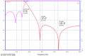
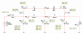
I'm using ngspice and KiCAD 8, but could just a well be using QSPICE. If it's of any use, I attached a KiCAD schematic, with a Bode plot, as a minimal example. [Sorry, learned that I couldn't post the schematic; wrong file type. Posted PDF instead.]

Thanks for any advice or guidance.


-Kevin
 

Attachments

0ri0n

Joined Jan 7, 2025
160
I’d like to design and model filters for the output of an amateur radio 100W HF transmitter. I don’t know how to model the transmitter itself.
200Vp voltage source with 50 Ohm in series.

Why does it have to be 100W? Do you want to determine the voltage/current burden of the individual filter components?
For Bode plots any 50 Ohm source will do. You could also plot S-parameters, like S21 and S11.
 

Thread Starter

kevinz

Joined Oct 26, 2022
6
It doesn't "have to be 100W," but that is both the size of the transmitter that I actually own, and the most common output of most amateur radio HF transmitters in the United States at this time.

Yes, I want to answer questions like:
What power dissipation must the resistor have, to not burn up?
What voltage value must the capacitor have, to not explode?
I'm not sure what a 'voltage/current burden' is; I've never heard this term before.

It's interesting that in another forum where I asked this same question, the answer was that V(RMS) = sqrt(R*P) for a 50 ohm antenna load. This calculates to 70.7V RMS, somewhat different from the answer provided of 200Vp, but still in the ballpark.

Thanks for responding to my question. I appreciate your help.

-Kevin
 

0ri0n

Joined Jan 7, 2025
160
It's interesting that in another forum where I asked this same question, the answer was that V(RMS) = sqrt(R*P) for a 50 ohm antenna load. This calculates to 70.7V RMS, somewhat different from the answer provided of 200Vp, but still in the ballpark.
Yes, that's correct, 70.71V RMS across a 50 Ohm load. For power matching another 70.71V RMS is dropped across the internal 50 Ohm resistance of the generator. This puts the open circuit voltage of the generator at 141.42V RMS or 200V peak.

An example that shows a 20m 5th-order elliptic lowpass filter is attached. Voltages and currents across respectively through the individual L/C components are shown. You can adjust the quality factor of the inductors and capacitors to more realistic values.
 

Attachments

WBahn

Joined Mar 31, 2012
32,702
It's interesting that in another forum where I asked this same question, the answer was that V(RMS) = sqrt(R*P) for a 50 ohm antenna load. This calculates to 70.7V RMS, somewhat different from the answer provided of 200Vp, but still in the ballpark.
The 70.7 Vrms is the voltage that needs to be applied to the 50 Ω load. But if you are modelling your source as an ideal voltage source in series with a 50 Ω output impedance that matches the load impedance, then that source impedance that's between the ideal source and load will drop another 70.7 Vms, making it so that you need about 141 Vrms output by the ideal source, which would require a sinusoidal output of 200 V amplitude.
 

MisterBill2

Joined Jan 23, 2018
27,159
The allowed output of an amateur transmitter is quite well defined legally as to the amplitude of both the intended signal and all of the unintended signal amplitudes.
The circuit of the output amplifier is usually quite well defined and is available in many publications.
 

MisterBill2

Joined Jan 23, 2018
27,159
Now a question I should have asked long ago: WHAT is the filter supposed to achieve?? A "perfect" transmitter would deliver a pure sine wave at the desired frequency. BUT the amplifier to provide that signal would not be very efficient. So many amateur transmitter amplifiers operate in class "C", which only delivers pulses of power that excite a resonant circuit at the required frequency and deliver an approximate sine wave. But there is a problem in that any wave not a perfect sine wave contains distortion products, including assorted harmonics. THAT is the reason that filters are required. The filter may simply ABSORB the harmonic energy, or possibly store it and deliver it as part of a pure sine wave. Either process results in power absorbtion and heating. Thus the problems.

So the TS needs to tell us about the signal to be passed and the distortion products that need to be stopped by the filter.
 
Top