Facebook
 Google
 GitHub
 Linkedin
Analog DC Reverse Loop Controller for Model Railway — Design Request
Background:
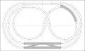
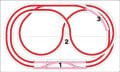
I am building a Z-scale analog DC model railway layout with 2 reverse loops. I need a controller circuit that automatically handles track polarity switching without DCC. The solution must work purely on analog DC track power.
The Problem:
A reverse loop on a 2-rail DC layout creates a polarity conflict at the isolation gap. The controller must resolve this by switching polarity in the correct section — either the reverse loop section or the main section — depending on whether the train is entering or exiting the loop.
Key Insight:
The system only needs one bit of state:
State OUTSIDE — train is on main section approaching loop → short circuit detected → flip reverse loop polarity → state becomes INSIDE
State INSIDE — train is in loop approaching main section → short circuit detected → flip main section polarity → state becomes OUTSIDE
This eliminates the need for optical sensors or directional detection.
Required Building Blocks:
Fast short circuit detector — must react faster than the analog power supply's own protection. Note: An LM393 dual comparator is suggested for the detection stage. If you know a better solution this is fine.
LM555 monostable — debounce/lockout timer after each trigger to ignore subsequent axle crossings. Timing adjustable, target 10-50ms
SR flip-flop or T flip-flop — holds one bit of state, toggles on each validated trigger
Two DPDT relays — one switches reverse loop section polarity, one switches main section polarity. Only one fires per trigger event, determined by flip-flop state
Relay driver transistors — to drive relay coils from logic level signals
Flyback diodes — across relay coils
Power-on reset — flip-flop must initialize to known state (OUTSIDE) at power-on
Operating Parameters:
Track voltage: 0-12V DC analog
Maximum track current: ~1A (Z scale)
Lockout time: adjustable 10-50 ms
Supply voltage for logic/relays: 12V DC separate from track power
Critical Design Constraints:
Short circuit detector must trip faster than power supply protection
After trigger, lockout must be long enough for all locomotive axles to clear the isolation gap at minimum running speed
Flip-flop state must be preserved during brief power fluctuations caused by the short circuit event itself.
If you notice any flaws in my logic, please let me know.
[CR] Human verified post.
Made with Claude assistance.
Background:
I am building a Z-scale analog DC model railway layout with 2 reverse loops. I need a controller circuit that automatically handles track polarity switching without DCC. The solution must work purely on analog DC track power.
The Problem:
A reverse loop on a 2-rail DC layout creates a polarity conflict at the isolation gap. The controller must resolve this by switching polarity in the correct section — either the reverse loop section or the main section — depending on whether the train is entering or exiting the loop.
Key Insight:
The system only needs one bit of state:
State OUTSIDE — train is on main section approaching loop → short circuit detected → flip reverse loop polarity → state becomes INSIDE
State INSIDE — train is in loop approaching main section → short circuit detected → flip main section polarity → state becomes OUTSIDE
This eliminates the need for optical sensors or directional detection.
Required Building Blocks:
Fast short circuit detector — must react faster than the analog power supply's own protection. Note: An LM393 dual comparator is suggested for the detection stage. If you know a better solution this is fine.
LM555 monostable — debounce/lockout timer after each trigger to ignore subsequent axle crossings. Timing adjustable, target 10-50ms
SR flip-flop or T flip-flop — holds one bit of state, toggles on each validated trigger
Two DPDT relays — one switches reverse loop section polarity, one switches main section polarity. Only one fires per trigger event, determined by flip-flop state
Relay driver transistors — to drive relay coils from logic level signals
Flyback diodes — across relay coils
Power-on reset — flip-flop must initialize to known state (OUTSIDE) at power-on
Operating Parameters:
Track voltage: 0-12V DC analog
Maximum track current: ~1A (Z scale)
Lockout time: adjustable 10-50 ms
Supply voltage for logic/relays: 12V DC separate from track power
Critical Design Constraints:
Short circuit detector must trip faster than power supply protection
After trigger, lockout must be long enough for all locomotive axles to clear the isolation gap at minimum running speed
Flip-flop state must be preserved during brief power fluctuations caused by the short circuit event itself.
If you notice any flaws in my logic, please let me know.
[CR] Human verified post.
Made with Claude assistance.
Last edited: