It's misleading. There are a huge number of third-party boards that are compatible. Arduino keeps a list of them here. The URL after the titles are the files that contain the information the IDE needs to install the support files for the board. They show up in the list of boards to select. Below is the Digistump section from the list. A note about the Digispark: you need a driver if you are using Windows but it gets installed during the IDE update; also, unlike most boards, you plug in the board to be programmed after the program has compiled. It prompts you and gives you 60 seconds to do it.
So what do I do in order to get the DigiSpark working? I want to put the code onto it... Do I add the URL for the DigiSpark into the Arduino web editor?
So what do I do in order to get the DigiSpark working? I want to put the code onto it... Do I add the URL for the DigiSpark into the Arduino web editor?
That's because the code he gave you is for the ATTINY85 not the ATTINY85 on a Digispark.
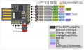
The program has to be adapted to match the pins on the board. Here is a diagram:
The numbers are the literal pin numbers but you can use the PBn numbers. Use PB1 in instead of D0 and PB2 instead of A1. Connect to the corresponding pins, they are marked on the bottom of the board.
So it appears that the definition of the Digispark development board does not include D0. D0 is a reserved word. It IS defined for the Arduino boards.
That doesn’t mean that you can’t use the Digispark. It DOES mean that the program must explicitly define D0 as the pin on the ATTiny85 that’s used for that function.
The numbers are the literal pin numbers but you can use the PBn numbers. Use PB1 in instead of D0 and PB2 instead of A1. Connect to the corresponding pins, they are marked on the bottom of the board.
I changed it in the code and hit upload. It told me to plug in the device and when I did, the computer kept giving the plug in and unplug noises over and over and Arduino never recognized the DigiSpark.
I changed it in the code and hit upload. It told me to plug in the device and when I did, the computer kept giving the plug in and unplug noises over and over and Arduino never recognized the DigiSpark.
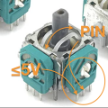
The dotted arrow is the axis of motion that will be measure. The stick moving within rather than against, the white plastic slot.
The unused pin is unused. The potentiometer is a variable resistor, it will be varying the voltage that appears on the analog pin. 5V in on the first pin, varying voltage out on the middle pin. The third pin is the other end of the resistor inside and we don't care about it.
The dotted arrow is the axis of motion that will be measure. The stick moving within rather than against, the white plastic slot.
The unused pin is unused. The potentiometer is a variable resistor, it will be varying the voltage that appears on the analog pin. 5V in on the first pin, varying voltage out on the middle pin. The third pin is the other end of the resistor inside and we don't care about it.

 Facebook
 Google
 GitHub
 Linkedin