Micro Joysticks In Place Of Dial On Servo Testers

Thread Starter

DragonTheta

Joined Feb 6, 2022
89
Thanks

It depends on which version you use:

View attachment 260543
That's because the code he gave you is for the ATTINY85 not the ATTINY85 on a Digispark.

The program has to be adapted to match the pins on the board. Here is a diagram:

The numbers are the literal pin numbers but you can use the PBn numbers. Use PB1 in instead of D0 and PB2 instead of A1. Connect to the corresponding pins, they are marked on the bottom of the board.
I'm wondering which pad on the DigiSpark is for D0

One of these posts says that it's P0 for D0

And the other post says that it's P1 for D0
 

Ya’akov

Joined Jan 27, 2019
10,356
Thanks


I'm wondering which pad on the DigiSpark is for D0

One of these posts says that it's P0 for D0

And the other post says that it's P1 for D0
I mentioned earlier:
The numbers [in the including pinout, see the original post] are the literal pin numbers but you can use the PBn numbers. Use PB1 in instead of D0 and PB2 instead of A1. Connect to the corresponding pins, they are marked on the bottom of the board.
You are not translating D0, you are using available pins on the Digispark that have the same function but are otherwise unrelated to the pins in the example code. It doesn’t matter what “D0” means except that is has a function which PB1 can do.

The PBn notation is what will work in your code and the physical connections on the board are correspondingly marked by the silkscreening on the underside.
 

Ya’akov

Joined Jan 27, 2019
10,356
Thank you


Would I use the same pinout if I were using the other potentiometer for the other axis

5 volt on the left signal in the middle and ground on the right
Yes, you can use the other axis in the same way. I chose that one because it looked like the easiest to constrain mechanically if you choose to modify it into a single axis with no center return.
 

Thread Starter

DragonTheta

Joined Feb 6, 2022
89
Thank you

I wired everything together and plugged it in. The motor twitched when I plugged it in but then stayed still. Movements of the joystick did nothing. I thought maybe it's because it's a single direction motor and it was maybe wired the wrong direction so I reversed two of the wires from the motor to the ESC which is supposed to reverse the motor direction. Again, when I plugged it in the motor twitched and then did nothing.
The pads where the motor is connected to the ESC are labeled with a 1 corresponding I assume to the s1 wire

https://drive.google.com/drive/folders/1KAzZPFLQr2zbFpn9zhCd2cAEPweDaRF5
 

Ya’akov

Joined Jan 27, 2019
10,356
Thank you

I wired everything together and plugged it in. The motor twitched when I plugged it in but then stayed still. Movements of the joystick did nothing. I thought maybe it's because it's a single direction motor and it was maybe wired the wrong direction so I reversed two of the wires from the motor to the ESC which is supposed to reverse the motor direction. Again, when I plugged it in the motor twitched and then did nothing.
The pads where the motor is connected to the ESC are labeled with a 1 corresponding I assume to the s1 wire

https://drive.google.com/drive/folders/1KAzZPFLQr2zbFpn9zhCd2cAEPweDaRF5
You are going to have to do some troubleshooting. I have to do some things here so I won't be around for a while. I will try to set up the same basic arrangement you have when I get the chance so I can see what it is doing.

In the meantime, you could read about using DigiKeyboard.h to simulate a serial monitor so you can see what the values are as the program runs. Larger boards have serial ports or can emulate them over the USB and the Arduino serial monitor can interact with them.

For the Digispark, a debugging trick is to have the board emulate a keyboard and have it type into something like Notepad so you can see the output. I am sure there are tutorials online, but I don't have time right now to find a good one.

When I get back I will try to recreate the frontend part of your setup here and look at what the code is doing. I can't really help with the ESC end, since I don't have one and haven't used one.

Sorry I can't help more right now.
 

Ya’akov

Joined Jan 27, 2019
10,356
OK, so here's some corrections and some instrumentation.

This is a modification of the original program. The important bits are on lines 8, 13, and 16.

Line 8: We need to use PB3 for the output. This is because PB1 has the on-board LED connected to it. We are going to use tat for diagnostic instrumentation (see: line 16).

Line 13: analogRead on the Digispark uses the number of the ADC rather than the pin. The ADC connected to PB2 is, not so intuitively "1". So we read from it with analogRead(1).

Line 16: This is our bit of instrumentation. Using the analogWrite() function, we will light the on-board LED proportional to the potentiometer's position as determined by the read from above. It uses the map() that scales val so it represents what should be applied to the PWM generation immediately after.

As you move the joystick the on-board LED will get brighter and dimmer if the program is reading it properly. This is a first test. If it works, then we can look elsewhere. Maybe @KeithWalker will have some advice.

I did wire up a Digispark and got a reasonable PWM waveform on the scope. The LED behaves as I want it to as well.

PWM Generator from [USER=459298]@KeithWalker[/USER] modified for Digispark:
 // Program an ATTINY85 to set position of servo by position of potentiometer.
 // Pot connected to pin A1, servo connected to pin D0

int val;

void setup()
{
  pinMode(PB3, OUTPUT);                     // Defines PB3 as output for servo
  digitalWrite (PB3, LOW);                  // Sets servo output low
}
void loop()
{
  val = analogRead(1);                     // Reads position of potentiometer from pin 2     
  val = map(val, 0, 1024, 1000, 2000);     // Scales the input range to pulse length values (uS)
 
  analogWrite (PB1, val-1000);             // Lights on-board LED with relative PWM value as an indicator

  digitalWrite (PB3, HIGH);                // Positive pulse
  delayMicroseconds (val);
  digitalWrite (PB3, LOW);
 
  delay (16);                              // Sets the frame rate
}
 

Thread Starter

DragonTheta

Joined Feb 6, 2022
89
// Program an ATTINY85 to set position of servo by position of potentiometer. // Pot connected to pin A1, servo connected to pin D0 int val; void setup() { pinMode(PB3, OUTPUT); // Defines PB3 as output for servo digitalWrite (PB3, LOW); // Sets servo output low } void loop() { val = analogRead(1); // Reads position of potentiometer from pin 2 val = map(val, 0, 1024, 1000, 2000); // Scales the input range to pulse length values (uS) analogWrite (PB1, val-1000); // Lights on-board LED with relative PWM value as an indicator digitalWrite (PB3, HIGH); // Positive pulse delayMicroseconds (val); digitalWrite (PB3, LOW); delay (16); // Sets the frame rate }
Thank you

I put the new code on the DigiSpark and plugged the battery in. It worked so that the joystick made the light fade in and out. It only took about 1/4 of the joystick's movement to get the light up to full. The ESCs made a ton of different beeps.
 

Ya’akov

Joined Jan 27, 2019
10,356
Thank you

I put the new code on the DigiSpark and plugged the battery in. It worked so that the joystick made the light fade in and out. It only took about 1/4 of the joystick's movement to get the light up to full. The ESCs made a ton of different beeps.
I don’t know about the ESC‘s beeps, but the potentiometer probably needs a resistor inline with it to scale the range. Do you have a DMM measure the resistance of the pot? The two outside pins will be the value of the pot.
 

Thread Starter

DragonTheta

Joined Feb 6, 2022
89
I don’t know about the ESC‘s beeps, but the potentiometer probably needs a resistor inline with it to scale the range. Do you have a DMM measure the resistance of the pot? The two outside pins will be the value of the pot.
DMM is that a multimeter

I would have to desolder everything off of the potentiometer in order to measure the resistance correct

So you're saying I should put one probe from a multimeter on each of the outside pins to check the resistance right
 

Ya’akov

Joined Jan 27, 2019
10,356
DMM is that a multimeter

I would have to desolder everything off of the potentiometer in order to measure the resistance correct

So you're saying I should put one probe from a multimeter on each of the outside pins to check the resistance right
Yes, a Digital Multimeter (DMM), You can measure the unused pot, it should be the same. Yes, the probe the two outside pins.

You really should invest in a breadboard and some Dupont wires, it would really make your life easier.
 

Thread Starter

DragonTheta

Joined Feb 6, 2022
89
Yes, a Digital Multimeter (DMM), You can measure the unused pot, it should be the same. Yes, the probe the two outside pins.

You really should invest in a breadboard and some Dupont wires, it would really make your life easier.

Thank you

I checked the outside pins of the unused potentiometer and it read 9.8 k

What are the breadboards and DuPont wires good for
 

Ya’akov

Joined Jan 27, 2019
10,356
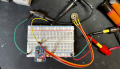
This is my test setup. I have soldered the headers onto the Digispark so the board can be plugged into the breadboard. I can change wiring at any time easily. I don't have to solder anything. If needed, additional components can be placed on the breadboard. The middle gap is intended to allow ICs to be used by straddling it.

1644918760985.png​
 

Ya’akov

Joined Jan 27, 2019
10,356
So, I don't mean to abandon you here but I really can't invest much more time right now in this project. I investigated @KeithWalker's code further and wasn't able to get a good PWM waveform on the scope. I don't know why. There are multiple parts involved and it could have been something wrong on my end.

In any case, I went on to try the TinySoftPWM library which works quite well but not without some troubles which could be my fault. Two things: the output voltage varies with frequency, though that might not matter. The second thing is just me not being able to spend the time to debug it, but the map() function apparently isn't properly scaling.

This really isn't a difficult problem but remote troubleshooting and not having the same hardware makes it much harder to help. If it is any consolation, a discrete logic version of this would be a lot harder for a neophyte, and with no hope of easily tuning it to work with your ESC. Keep at it, there is information on the web and I am hoping others here will be able to step in. I simply must step out, for now, at least.

Below is the program using the library. It produces proper PWM and it used by many other people. It might be a start. I would at least see if your ESC is more happy with its output. It is almost certainly not ready for use, but I suspect the potentiometer I was using might be unreliable.

PWM Generator using TinySoftPWM:
/* Cobbled together from the library example code for a test. It produces a good PWM waveform
*  The library code is here: https://github.com/digistump/DigisparkArduinoIntegration/tree/master/libraries/DigisparkTinySoftPwm
*/

#include <TinySoftPwm.h>

int val;

void setup() {
  pinMode(PB3, OUTPUT);                     // Defines PB3 as output
  TinySoftPwm_begin(128, 0); /* 128 x TinySoftPwm_process() calls before overlap (Frequency tuning), 0 = PWM init for all declared pins */
}

void loop()
{
static uint32_t StartUs=micros();
static uint32_t StartMs=millis();
static uint8_t Pwm=0;
static int8_t  Dir=1;

  /***********************************************************/
  /* Call TinySoftPwm_process() with a period of 60 us       */
  /* The PWM frequency = 128 x 60 # 7.7 ms -> F # 130Hz      */
  /* 128 is the first argument passed to TinySoftPwm_begin() */
  /***********************************************************/
  if((micros() - StartUs) >= 60)
  {
    /* We arrived here every 60 microseconds */
    StartUs=micros();
    TinySoftPwm_process(); /* This function shall be called periodically (like here, based on micros(), or in a timer ISR) */
  }

  /*************************************************************/
  /* period of 10 ms */
  /*************************************************************/
  if((millis()-StartMs) >= 10)
  {
    StartMs=millis();
  
    Pwm = analogRead(1);                     // Reads position of potentiometer from pin 2
    Pwm = map(Pwm, 0, 1023, 0, 255);;      // Scales the input range to PWM parameter 
    TinySoftPwm_analogWrite(PB3, Pwm);       // Writes to output
    TinySoftPwm_analogWrite(PB1, Pwm);       // Writes to built in LED
  }
}
 

Thread Starter

DragonTheta

Joined Feb 6, 2022
89
So, I don't mean to abandon you here but I really can't invest much more time right now in this project. I investigated @KeithWalker's code further and wasn't able to get a good PWM waveform on the scope. I don't know why. There are multiple parts involved and it could have been something wrong on my end.

In any case, I went on to try the TinySoftPWM library which works quite well but not without some troubles which could be my fault. Two things: the output voltage varies with frequency, though that might not matter. The second thing is just me not being able to spend the time to debug it, but the map() function apparently isn't properly scaling.

This really isn't a difficult problem but remote troubleshooting and not having the same hardware makes it much harder to help. If it is any consolation, a discrete logic version of this would be a lot harder for a neophyte, and with no hope of easily tuning it to work with your ESC. Keep at it, there is information on the web and I am hoping others here will be able to step in. I simply must step out, for now, at least.

Below is the program using the library. It produces proper PWM and it used by many other people. It might be a start. I would at least see if your ESC is more happy with its output. It is almost certainly not ready for use, but I suspect the potentiometer I was using might be unreliable.

PWM Generator using TinySoftPWM:
/* Cobbled together from the library example code for a test. It produces a good PWM waveform
*  The library code is here: https://github.com/digistump/DigisparkArduinoIntegration/tree/master/libraries/DigisparkTinySoftPwm
*/

#include <TinySoftPwm.h>

int val;

void setup() {
  pinMode(PB3, OUTPUT);                     // Defines PB3 as output
  TinySoftPwm_begin(128, 0); /* 128 x TinySoftPwm_process() calls before overlap (Frequency tuning), 0 = PWM init for all declared pins */
}

void loop()
{
static uint32_t StartUs=micros();
static uint32_t StartMs=millis();
static uint8_t Pwm=0;
static int8_t  Dir=1;

  /***********************************************************/
  /* Call TinySoftPwm_process() with a period of 60 us       */
  /* The PWM frequency = 128 x 60 # 7.7 ms -> F # 130Hz      */
  /* 128 is the first argument passed to TinySoftPwm_begin() */
  /***********************************************************/
  if((micros() - StartUs) >= 60)
  {
    /* We arrived here every 60 microseconds */
    StartUs=micros();
    TinySoftPwm_process(); /* This function shall be called periodically (like here, based on micros(), or in a timer ISR) */
  }

  /*************************************************************/
  /* period of 10 ms */
  /*************************************************************/
  if((millis()-StartMs) >= 10)
  {
    StartMs=millis();
 
    Pwm = analogRead(1);                     // Reads position of potentiometer from pin 2
    Pwm = map(Pwm, 0, 1023, 0, 255);;      // Scales the input range to PWM parameter
    TinySoftPwm_analogWrite(PB3, Pwm);       // Writes to output
    TinySoftPwm_analogWrite(PB1, Pwm);       // Writes to built in LED
  }
}

Thank you

The code actually made the motor spin. The joystick went through about 3/4 of its range of motion from 0 to 75 and then the light on the digi spark started to turn on. At that point the ESC beeped and the motor started to twitch. At 100% of the joysticks throttle movement, the LED was on fully bright and the motor would spin and turn off, spin and turn off in short bursts.
 

Ya’akov

Joined Jan 27, 2019
10,356
Thank you

The code actually made the motor spin. The joystick went through about 3/4 of its range of motion from 0 to 75 and then the light on the digi spark started to turn on. At that point the ESC beeped and the motor started to twitch. At 100% of the joysticks throttle movement, the LED was on fully bright and the motor would spin and turn off, spin and turn off in short bursts.
I believe the scaling of the 0-1024 from the analog read to the 0-256 of the PWM needs work. But the library produces good signals. I noticed the library example had something like “RC KING” in the comments at the top which suggests there might be someone who is both expert in the library and your application. If you go to that link and look at the example, there might be contact information, or enough to make a successful search.

I wish you luck with this, you are very close to a solution but the devil is in the details. Once it is working, the refinement will be both eas(ier) and satisfying. I strongly suggest you do your very best to understand what any code you copy or use is actually doing and why. Blindly copying code, called cargo culting is the cause of many problems and few solutions.

If you make progress and have pointed questions about details, I will probably be able to help. Best of luck, I think you will have a good outcome, you have the right parts.
 

Thread Starter

DragonTheta

Joined Feb 6, 2022
89
Hello,

I set up a DigiSpark with a four-in-one RC electronic speed controller and a micro joystick. Here's the hardware:

https://drive.google.com/drive/folders/1KAzZPFLQr2zbFpn9zhCd2cAEPweDaRF5?usp=sharing

I tried this code for getting the micro joystick to control the throttle of a brushless motor. The LED turned on at about 75% throttle, and the motor started to twitch at that point. The ESC beeped at that point also. When I increased the throttle, the motor kept turning off and on in short bursts, mostly off. Going back and forth past approximately the 75% throttle mark made the ESC beep a lot, with multiple different types of beeping pattern.
The one who gave me the code said "I believe the scaling of the 0-1024 from the analog read to the 0-256 of the PWM needs work."

I don't know how to post the code with the proper setup


/* Cobbled together from the library example code for a test. It produces a good PWM waveform
* The library code is here: https://github.com/digistump/DigisparkArduinoIntegration/tree/master/libraries/DigisparkTinySoftPwm
*/

#include <TinySoftPwm.h>

int val;

void setup() {
pinMode(PB3, OUTPUT); // Defines PB3 as output
TinySoftPwm_begin(128, 0); /* 128 x TinySoftPwm_process() calls before overlap (Frequency tuning), 0 = PWM init for all declared pins */
}

void loop()
{
static uint32_t StartUs=micros();
static uint32_t StartMs=millis();
static uint8_t Pwm=0;
static int8_t Dir=1;

/***********************************************************/
/* Call TinySoftPwm_process() with a period of 60 us */
/* The PWM frequency = 128 x 60 # 7.7 ms -> F # 130Hz */
/* 128 is the first argument passed to TinySoftPwm_begin() */
/***********************************************************/
if((micros() - StartUs) >= 60)
{
/* We arrived here every 60 microseconds */
StartUs=micros();
TinySoftPwm_process(); /* This function shall be called periodically (like here, based on micros(), or in a timer ISR) */
}

/*************************************************************/
/* period of 10 ms */
/*************************************************************/
if((millis()-StartMs) >= 10)
{
StartMs=millis();

Pwm = analogRead(1); // Reads position of potentiometer from pin 2
Pwm = map(Pwm, 0, 1023, 0, 255);; // Scales the input range to PWM parameter
TinySoftPwm_analogWrite(PB3, Pwm); // Writes to output
TinySoftPwm_analogWrite(PB1, Pwm); // Writes to built in LED
}
}
 
Last edited:

Thread Starter

DragonTheta

Joined Feb 6, 2022
89
Since I'm not seeing any more answers here or on the Arduino forums about the code, I'm going back to the original idea of using servo testers. At some point I might hire a consultant to do the code for me, but for now I am going to explore the servo testers idea.

I got the servo tester hooked up with the 5 volt and ground into the servo tester coming from the ESC, and the signal out from the servo tester going to the ESC, and plugged in a battery. The ESC beeped a lot but the servo tester did not control the motor. The motor just stayed off.
 

djsfantasi

Joined Apr 11, 2010
9,237
Since I'm not seeing any more answers here or on the Arduino forums about the code, I'm going back to the original idea of using servo testers. At some point I might hire a consultant to do the code for me, but for now I am going to explore the servo testers idea.

I got the servo tester hooked up with the 5 volt and ground into the servo tester coming from the ESC, and the signal out from the servo tester going to the ESC, and plugged in a battery. The ESC beeped a lot but the servo tester did not control the motor. The motor just stayed off.
Servo testers are built for the purpose of testing a hobby RC servo. Their output is one cycle every 20 ms and is on for somewhere between 1 & 2 ms.

I doubt that they can effectively be used to control an ESC which expects a signal on from 0 to 100% of each cycle. The best you’ll get out of the servo tester is 10% ( 2ms / 20ms = 10% )

This would give you about a 0.5V output from the ESC (10% of 5V). Which likely won’t move the servo motor.

The code examples you’ve been given should work, if the microprocessor is wired correctly, pin assignments in the code are correct, the pot is of good quality…

So as Yaakov said, it’s impossible or at best strongly unlikely that this can be debugged remotely. Sorry, I’m out as well.
 
Top