measure HIGH AC current with an Arduino

dendad

Joined Feb 20, 2016
4,641
It sounds like there is something wrong with your sensing setup. If you are getting only 3mV for your voltage measurement you need a longer length of cable or check you amplifier circuit.
Try to just measure across the full length of one cable to see what volts you get. I would expect even a multimeter would read something across one full cable unless you have really good cables.
 

strantor

Joined Oct 3, 2010
6,875
Ok so I did as you said and the resistance at the cross section is 0.002Ω and the voltage at the cross section during a weld is 0.0030V for 60ms

So doing the math would be
I = 0.003/0.002
= 1.5A

Really ?
Your math here looks correct.
well i got a bit lost with working on it.

I've measured the transformers secondary resistance with the Kelvin technique and it reads 0.00537Ω.

Calculation
V = 0.0067v (probing 13cm apart on the cable with a DMM) for 60ms pulse
R = 0.00537Ω
I = V/R
= 1,247Aamps
Your previous math here does NOT look correct, I just noticed.
I = .0067/.00537
= 1.248A

We need to confirm these numbers are not actually correct. So when you perform the test, what happens?
Do you hear a very loud noise from the transformer? is there a lot of heat generated at the weld spot? How many amps is the transformer primary drawing?
 

Thread Starter

anishkgt

Joined Mar 21, 2017
549
I take it you are asking about measuring the voltage across the electrodes to work out the current.
You only need to measure the voltage across a short length of one cable to work out the current. A longer length will give you more voltage to play with so you may not need an amplifier to get enough volts to measure. You are measuring the voltage across a resistor in series with the load to work out the current. A longer part of the lead is a higher resistance.
Measuring across the full length is ok, as long as you use Kelvin connections so as not to add the voltage drop of the terminals to your reading.
BUT if you measure across the electrodes, the measurement will be your supply voltage not the current when the electrodes are open, and the voltage across the joint being welded when closed. And as the weld joint is an unknown highly variable value, it is useless for calculating the current.
Current measurement needs to be taken from ONE wire only. There is no point on connecting to both wires as the current will be the same in the series circuit but if you take your measurement across both wires it will be meaningless.
I suppose you could measure the volts at the transformer end, then subtract the volts measured at the electrode end then using the difference, work out the current but why do it that way? Just the voltage drop across a sample of one cable is all you need and the easiest way to do it.

Thank you dendad for taking time to clearing my concerns. strantor has been putting up with me for all my silly noob questions but without him i wouldn't have understood it this far.

I am using my Brymen BM869s to take a voltage at two points on the cable but as i do i get a reading when open as well. I guess i was doing it wrong. As you say i should only probe at one point on the cable somewhere between the electrodes, correct ? so what where does the other probe of the DMM go ? at the other electrode if am correct. That way a circuit is complete for the DMM.
 

strantor

Joined Oct 3, 2010
6,875
welder.png
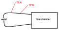
You pick 2 points along the weld lead as shown. Measure the resistance between Test Point A and Test Point B. during the weld, measure voltage between the same Test Point A and Test Point B, and use those numbers to calculate Amps. Is that how you're doing it?
 

Thread Starter

anishkgt

Joined Mar 21, 2017
549
It sounds like there is something wrong with your sensing setup. If you are getting only 3mV for your voltage measurement you need a longer length of cable or check you amplifier circuit.
Try to just measure across the full length of one cable to see what volts you get. I would expect even a multimeter would read something across one full cable unless you have really good cables.
The open voltage is 2.56VAC. I am waiting for a double sided pcb to arrive so i haven't etched a board to use the circuit. As of now am just using my DMM to get the resistance via the kelvin method and measure the voltage at the section of the cable.

Do you hear a very loud noise from the transformer? is there a lot of heat generated at the weld spot? How many amps is the transformer primary drawing?
To test that i removed it from the pcb and connected to the mains and there is a very low hum with an open voltage of 2.56VAC. With my exisitng (without the current sense circuit) pcb the spot welding works when welding nickel strips on 18650 cells. That is a dual pulse first pulse being 10ms and second being 60ms. The joint is never hot cold and i can see it glow when as the welding occurs.
 

Thread Starter

anishkgt

Joined Mar 21, 2017
549
View attachment 136990
You pick 2 points along the weld lead as shown. Measure the resistance between Test Point A and Test Point B. during the weld, measure voltage between the same Test Point A and Test Point B, and use those numbers to calculate Amps. Is that how you're doing it?

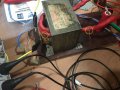
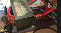
That is exactly how am doing it but both taps are near the core and one of them being closer to the primary. As seen in the attached
1.jpg 2.jpg
 

dendad

Joined Feb 20, 2016
4,641
As strantor showed above, you use both probes on the one cable.
Your previous posts indicated to me you were talking about measuring with one probe on each cable.
And if you are getting the same reading with it welding or not there is something wrong.
While I have not used a Brymen BM869s, it looks pretty good.
Are you using the mV AC range?
 

dendad

Joined Feb 20, 2016
4,641
That is exactly how am doing it but both taps are near the core and one of them being closer to the primary. As seen in the attached
View attachment 136991 View attachment 136992
I would think it better to not have your taps each side of the transformer but both in the wire external to it on one side.
You will be getting some voltage induced into the wire by the transformer and you do not want to measure that but only the voltage dropped by the current. It may be worth while havng longer leads. They certainly look big enough.
 

strantor

Joined Oct 3, 2010
6,875
That is exactly how am doing it but both taps are near the core and one of them being closer to the primary. As seen in the attached
View attachment 136991 View attachment 136992
No, you're not doing it exactly the same. The way you're doing it, you're measuring from one side of a transformer winding to the other side, with a transformer core in between. you have a small voltage source in between your two test points. get rid of that test point in the middle of the winding and move it to the end of your lead as shown:

welder.png
 

strantor

Joined Oct 3, 2010
6,875
It may be worth while havng longer leads. They certainly look big enough.
I disagree; they could be larger gauge, and the shorter the better. Remember the goal here is to have multiple thousands of amps flowing at low voltage. even a cable that big is a considerable resistor on these scales.
 

Thread Starter

anishkgt

Joined Mar 21, 2017
549
Thanks strantor.
I've moved one tap closer to the electrode and I get a ohm reading of 0.0006 @ 1A

Will do a weld and check the current with these values.
 

Thread Starter

anishkgt

Joined Mar 21, 2017
549
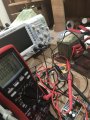
I guess am doing something wrong.

I see the voltage varying when dmm is is probed in AC voltage mode and due to that I cannot get the actual reading when welding.

image.jpg
 

dendad

Joined Feb 20, 2016
4,641
You are saying "....in AC voltage mode", does that mean you are changing the multimeter mode when welding?
It still should be ACV.
I may just be misunderstanding you, sorry if so.
 

strantor

Joined Oct 3, 2010
6,875
You need to continue the weld for at least a couple of seconds. Your meter is probably trying to do some math and needs several Cycles in order to give you an accurate reading
 

dendad

Joined Feb 20, 2016
4,641
Have you a length of cable spare?
If so, see if you can add that to the cable there to just test a longer bit. It will give you a higher voltage signal to work with.
Also, it could be your multimeter cannot respond fast enough. You are only running for 60mS I think you said. Some meters sample over a longer period. Try MAX setting if your meter has that and it may capture it better.
 

Thread Starter

anishkgt

Joined Mar 21, 2017
549
You need to continue the weld for at least a couple of seconds. Your meter is probably trying to do some math and needs several Cycles in order to give you an accurate reading
Then shorting the ends would be better if that is what you mean by 'longer'
 

Thread Starter

anishkgt

Joined Mar 21, 2017
549
Have you a length of cable spare?
If so, see if you can add that to the cable there to just test a longer bit. It will give you a higher voltage signal to work with.
Also, it could be your multimeter cannot respond fast enough. You are only running for 60mS I think you said. Some meters sample over a longer period. Try MAX setting if your meter has that and it may capture it better.
The dmm has a min max and avg mode to capture pulse and yes I do have a longer cable as well. But wanted to fit inside a housing and keep the cable short was what I had in mind. Will try rewinding the secondary with a longer one as you say.
 

Thread Starter

anishkgt

Joined Mar 21, 2017
549
I just did quick test with the leads shorted and run it several times and got a 5mv.

How do we know how much voltage is enough ?
 

strantor

Joined Oct 3, 2010
6,875
The dmm has a min max and avg mode to capture pulse and yes I do have a longer cable as well. But wanted to fit inside a housing and keep the cable short was what I had in mind. Will try rewinding the secondary with a longer one as you say.
Please don't. You need the leads as short as possible.
 
Top