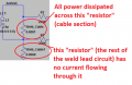
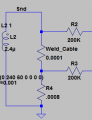
I don't understand why you're measuring Open Circuit Voltage. OCV will godown as current goes up. That's not the same thing as measuring across a section of welding lead. Look at the way I drew it; measured across a shunt (a section of welding lead)
yea i had resolved it earlier. The precision thingy does not seem to be precise as it says, probably the henry parameter in the transformer that i may have got wrong.
I don't understand why you're measuring Open Circuit Voltage. OCV will godown as current goes up. That's not the same thing as measuring across a section of welding lead. Look at the way I drew it; measured across a shunt (a section of welding lead)
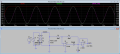
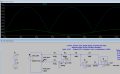
So did some poking around with the probe and found that adding a ground for power source gave sine wave and now the the output seems to be a square wave.
On second thought, why add a first opamp when the existing gives the actual rectified voltage in AC and adding a 18uf 10v would smoothen it and then fed into MCU and have it scaled to 5v.
A current transformer would normally have LESS turns on its primary than on it's secondary. For high currents such as you are mesuring (I assume several hundred amps.) the primary is just the conductor passing through a toroidal core with a large number of turns on the secondary. So if you had 1000 turns on the secondary the secondary current would be 1 mA for each amp through the primary. You need a relativly low value across the secondary. (to ensure the core does not saturate.) If you used a 10 ohm resistor across the secondary you should see 10 mV across it for each amp of current in the primary.
A current transformer would normally have LESS turns on its primary than on it's secondary. For high currents such as you are mesuring (I assume several hundred amps.) the primary is just the conductor passing through a toroidal core with a large number of turns on the secondary. So if you had 1000 turns on the secondary the secondary current would be 1 mA for each amp through the primary. You need a relativly low value across the secondary. (to ensure the core does not saturate.) If you used a 10 ohm resistor across the secondary you should see 10 mV across it for each amp of current in the primary.
thanks Les. I just omitted the idea of a Xfrm and just went with a 3VAC sine wave, now the precision rectifier has some problem outputing the same volts.
Ok, but now you're measuring OCV again. That's not going to give you higher voltage for higher amps and lower voltage for lower amps. It's going to give you higher voltage for lower amps and lower voltage for higher amps. But I guess you could reverse scale that in the microcontroller. would be kinda klugey but probably workable.
A current transformer would normally have LESS turns on its primary than on it's secondary. For high currents such as you are mesuring (I assume several hundred amps.) the primary is just the conductor passing through a toroidal core with a large number of turns on the secondary. So if you had 1000 turns on the secondary the secondary current would be 1 mA for each amp through the primary. You need a relativly low value across the secondary. (to ensure the core does not saturate.) If you used a 10 ohm resistor across the secondary you should see 10 mV across it for each amp of current in the primary.
So did some poking around with the probe and found that adding a ground for power source gave sine wave and now the the output seems to be a square wave.
On second thought, why add a first opamp when the existing gives the actual rectified voltage in AC and adding a 18uf 10v would smoothen it and then fed into MCU and have it scaled to 5v.
Adding the first opamp is because you're not supposed to be measuring voltage in the ~3V range. You're not supposed to be measuring OCV. OCV is inversely proportional to amps. You're supposed to be measuring the voltage drop across a section of conductor with known resistance (as you did in your very first post), that will be directly proportional with amps, and that signal will be very small, millivolts. It will need to be amplified to 5V full scale into the microcontroller. In hindsight, it would probably be better to put it after the rectifier section so that you could get away with just using single supply.. I will play with the sim again and see if I can make it work.
OK sorry I was half asleep last night when I made the circuit, and I forgot why I did what I did. the reason I put the new opamp before the rectifier section is because I set it up as a difference amplifier to read across the shunt (section of cable). there's no good way to move it to the other side. you would need dual supplies as I said earlier.
I installed a -5V supply for the new opamp and now you can see the mV AC signal across the weld lead section turned into a 3.5V pulse. You can add whatever cap you were using to the output to make it a DC signal.
Adding the first opamp is because you're not supposed to be measuring voltage in the ~3V range. You're not supposed to be measuring OCV. OCV is inversely proportional to amps. You're supposed to be measuring the voltage drop across a section of conductor with known resistance (as you did in your very first post), that will be directly proportional with amps, and that signal will be very small, millivolts. It will need to be amplified to 5V full scale into the microcontroller. In hindsight, it would probably be better to put it after the rectifier section so that you could get away with just using single supply.. I will play with the sim again and see if I can make it work.
Thank you for explaining that to me. Appreciate that. It really made sense when when i measured the way i did earlier the OCV way. It would give a reading every time i switched on the SCR without spot welding and was a bit confused how it did when there was no contact between then electrodes.
the reason I put the new opamp before the rectifier section is because I set it up as a difference amplifier to read across the shunt (section of cable). there's no good way to move it to the other side. you would need dual supplies as I said earlier.
I get confused with voltage dividers. I guess i never understood it very well.
Why do we have two weld leads ? The first op-amp would measure the voltage drop at taps on the weld cable 13cm apart and what is the second lead with resistance of .0008Ohm ? Smoothing the rectified would be bad idea as there would be some offset hence doing an RMS calculation withing the software would be better. That was a suggestion from here.
I installed a -5V supply for the new opamp and now you can see the mV AC signal across the weld lead section turned into a 3.5V pulse. You can add whatever cap you were using to the output to make it a DC signal.
I doubt that would be possible for me to do as i am running out off space in my design. Unless i design another break-out board for current measurement.Moreover those extra opamp and the components for it is adding more cost.
I thought just get that voltage would just do the trick and use the formula i had posted earlier to get the current and use Ohms law to get the resistance. seems it was not as simple as i thought.
The reason I put the new opamp before the rectifier section is because I set it up as a difference amplifier to read across the shunt (section of cable). there's no good way to move it to the other side. you would need dual supplies as I said earlier. I get confused with voltage dividers. I guess i never understood it very well.
Why do we have two weld leads ? The first op-amp would measure the voltage drop at taps on the weld cable 13cm apart and what is the second lead with resistance of .0008Ohm ? Smoothing the rectified would be bad idea as there would be some offset hence doing an RMS calculation withing the software would be better. That was a suggestion from here.
Ok i seem to get what the second weld lead is for. its actually just to show in theory that the remaining current flowing back to complete the circuit. How well would this be applicable omitting that one opamp at the beginning.
Hey man good stuff. That's what I was trying to do in my first few replies here but couldn't figure out how to eliminate the 3rd opamp. Looks like you got it figured out. Congrats!
P.s. the LT1078 comes in dual and even quad packages so you'll only need to add a single IC to your design and a few resistors (assuming you already have 5v power).
Hey man good stuff. That's what I was trying to do in my first few replies here but couldn't figure out how to eliminate the 3rd opamp. Looks like you got it figured out. Congrats!
P.s. the LT1078 comes in dual and even quad packages so you'll only need to add a single IC to your design and a few resistors (assuming you already have 5v power).
Wait, wait, wait. When I looked at this last night I missed something. This morning I played in LTSpice with the circuit you posted and realized that you've made a booboo and the only reason it works is because your transformer is a "perfect" simulation transformer and has no impedence. Here's the booboo:
Your circuit should look like this:
Now you have current flowing through the whole weld circuit, and now the rectifier/amplifier doesn't work properly.
I think you are going to need the 3 opamps. Unless someone more clever than you or I can come along and advise.
yes the ratio (henries) is correct, good enough for simulation. but unless you input real-world values for series & parallel resistance, capacitance, and inductance, the simulated transformer will behave as a "perfect" transformer and the simulation will not show voltage drop from the transformer as we see in real life. If you want to fully simulate your actual transformer you would need to measure these values with an LCR meter and input to the simulation. But in my opinion this is not really necessary for what we have discussed thus far. Maybe in the future you would get some use of doing it but it's not critical now.

 Facebook
 Google
 GitHub
 Linkedin




 . Just poke around and something would work.