measure HIGH AC current with an Arduino

dendad

Joined Feb 20, 2016
4,641
A few tests to do to confirm a real reading...
Swap the meter probes and see if your reading goes to the same but the reverse polarity. That can indicate it is a real reading, and not just noise.
When the power supply is turned off, the reading should be zero.
Increase the current and see if the measured voltage increases in proportion.
Leave the power supply turned on and remove one clip from your power supply. Now your reading should be zero also. If not, you are probably measuring noise.

And my faverite one , repeat running the same current through the full length of your spare cable. Then you have a larger reading. If this reading is 0.03mV x times longer than the distance between your test points you then have a pretty good indication that it is correct.
Now you have a confirmed reading for 1amp ( or whatever the test current was) so you can work out what gain the sense active rectifier amp needs to have to give you a good reading for the analog input of the Arduino.
 

Thread Starter

anishkgt

Joined Mar 21, 2017
549
Swap the meter probes and see if your reading goes to the same but the reverse polarity. That can indicate it is a real reading, and not just noise.
When the power supply is turned off, the reading should be zero.
Yes I get a negative reading when swapping the probes and a zero reading when one of the power source terminals are removed. The mV does increment proportionally as I increase the current.

Secondly I had a 112inch of the same wire laying around and the resistance is 213Ω.

Now you have a confirmed reading for 1amp ( or whatever the test current was) so you can work out what gain the sense active rectifier amp needs to have to give you a good reading for the analog input of the Arduino.
I did not understand clearly this part, so i should have a gain of how much ? Like 2 or 3 ?
 

dendad

Joined Feb 20, 2016
4,641
If you are going to get around 36mV for 1000A, to get a good reading on the Arduino, this signal needs to be amplified. 36mV RMS is about 50mV peak so an amp of a gain of 100 will give 5V peak. As you hope to go over 1000Amps, if your core can do it, maybe have a gain of 50 and that will give you plenty of headroom.
Build the active rectifier and see what DC you can get. On the system we designed for a generic analog in, we had an active rectifier with a large range of gain adjustment via a multi turn trim pot. The output was clamped to 5V max and fed into a PIC. This was used for current transformer inputs, 4-20mA in and 0-10V inputs. Tomorrow I can hunt up the circuit if you like. This circuit has been in good use for close to 20 years now and in fact is still used in a lot of our installations. I think it will work well for your current measuremant. The output goes to a tantulum capacitor so it holds the peak reading quite long enough for a reading to be taken.
 

Thread Starter

anishkgt

Joined Mar 21, 2017
549
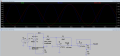
In the beigining or half way through we had decided upon an iSense circuit with the LT1078, a cap and two diodes which was used as a precision rectified and part of Dave’s (from eevblog youtube channel) idea about peak detectors.
 

strantor

Joined Oct 3, 2010
6,875
OK so I did some math:
3AWG wire has a resistivity of 0.6465 milliohms/meter.
Looks like you have about a meter of it there as your secondary so We'll say you're working with 0.6465 milliohms internal resistance.
At 2.56V, This will limit your output to:
2.56/0.0006465 = 3960A maximum theoretical output.
2.56V * 3960A = 10,138W

Unfortunately, you aren't going to get anywhere near 10kW out of that tiny transformer. The original microwave is probably not rated more than 1.1kW.
I think the maximum you can realistically hope for is maybe 800A output (about 2kW output).
I arrive at this 800A number empirically, from my own microwave oven transformer experiments.
I tried making my spot welder using only 1 transformer previously, and ended up moving to a 3 transformer design because I couldn't get more than 800A out of just 1 transformer.

So I think it is safe to design for 4V output @ 30mV. Since your supply is only 5V, we should not expect to get 5V full scale from the opamp, and we should not expect to see a full 1000A.
Given that, I have adjusted some resistor values in the simulation:


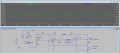
upload_2017-10-11_8-51-56.png

I had to change R1 to 240K to eliminate a slight unbalance in the rectification due to the smaller mV signal.
I changed the gain of the final opamp (R3/R6)
I changed the value of the shunt (Weld_cable) to match your actual, and I changed the value of R4 (the rest of the weld circuit) to give 800A max.
 

Attachments

Thread Starter

anishkgt

Joined Mar 21, 2017
549
Thanks you for taking time to help me with the schematic.

So basically to get the amp reading we need the resistance of the weld cable (end-to-end) and a voltage reading from section of the cable and calculate the remaining with Ohms law.

My calculation earlier gave about 2.6 or something in that range, would that be in Amps or mA. For Amps that would be very low, wouldn't it ? isn't that 2600Amps.

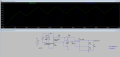
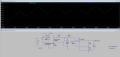
Here is a more rectified schematic with a cap to smooth out the signal.
SPW.PNG
 

Attachments

strantor

Joined Oct 3, 2010
6,875
So basically to get the amp reading we need the resistance of the weld cable (end-to-end) and a voltage reading from section of the cable and calculate the remaining with Ohms law.
NO. I only calculated the resistance of the weld cable (end-to-end) to come up with a theoretical maximum amp output of the machine based on internal resistance. I should not have done that; I think it was more confusing. You need the resistance of the 5.5cm section of weld cable, and the voltage drop across the 5.5cm section, and use Ohm's law based on that.

My calculation earlier gave about 2.6 or something in that range, would that be in Amps or mA. For Amps that would be very low, wouldn't it ? isn't that 2600Amps.
I don't know what calculation you're referring to, and I don't know what your number 2.6 signifies. But I can guarantee you aren't getting anywhere near 2,600A from that thing.
 

strantor

Joined Oct 3, 2010
6,875
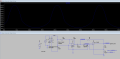
I've taken your sim and made some changes to it to bring it back into fitting the criteria of a precision rectifier. You wanted a capacitor smoothed output, well this circuit won't give you that. your flat line that you saw in your sim wasn't real. this is what it looks like with capacitor smoothing:
upload_2017-10-11_11-51-54.png

I chose 50µf because anything higher gives you a smoother line, but it takes several cycles to reach steady state. This application needs fast response, and a capacitor won't do that.

If you really need a flat line DC output then you're going to need to start over with a new circuit. Let's see what @dendad has up his sleeve.
 

Attachments

Thread Starter

anishkgt

Joined Mar 21, 2017
549
The schematic is based on the video series done by Dave in his YouTube channel. Their he explains the idea behind it.

I understood then and their and incorporated it. I am no expert with Opamps but what i understand is that the 0.1uf does not take much to charge and that keeps the steady voltage for the MCU.
 

Thread Starter

anishkgt

Joined Mar 21, 2017
549
I only calculated the resistance of the weld cable (end-to-end) to come up with a theoretical maximum amp output of the machine based on internal resistance. I should not have done that; I think it was more confusing. You need the resistance of the 5.5cm section of weld cable, and the voltage drop across the 5.5cm section, and use Ohm's law based on that.
When you said "I only calculated the resistance of the weld cable (end-to-end) to come up with a theoretical maximum amp output of the machine based on internal resistance" you mean the max amps that the xfrmer can put out, correct ?

I meant for this application at different timing as in 20, 40 or 50ms. The 5.5cm section is taken only to read the voltage difference and used to calculate the amps put out at a given time with given resistance (0.03Ω) taken when applying a 1A current at the ends of the secondary and measure the voltage drop across 5.5cm section of the cable. That way we have the V and R of the Ohms law to find ' I '. With that said i get a 2.99mVAC at 80ms, doing the math
I = V/R
= 0.00299/0.03
= 0.099A

Really ?? i am sure that would be wrong because i could see the nickel spots getting red hot while welding and the weld is very strong and as per the above calculation that would not happen at 0.099A
 
Top