measure HIGH AC current with an Arduino

dendad

Joined Feb 20, 2016
4,641
If that reading of 5mV is repeatable it will be enough to feed into an amplifier/active rectifier to scale to a suitable reading for the Arduino to read.
If you could get a higher AC reading it woulds be better as then there would be a greater difference between the signal and the noise level.
A longer bit of cable between the transformer and the electrode will make it easier but why not try an amplifier on what you have and see how it goes?
 

strantor

Joined Oct 3, 2010
6,875
@dendad before repeating your recommendation of lengthening the leads again, please run the numbers on that, and understand the ramifications of what you are recommending.
 

dendad

Joined Feb 20, 2016
4,641
Please don't. You need the leads as short as possible.
I would not get so hung up on the absolute minimum lead length. Those leads are plenty big enough in diameter. The spot welders I have seen all have a meter or so of external cable. And you have seen the result of very short cable not giving enough voltage drop reading.
 

strantor

Joined Oct 3, 2010
6,875
I just did quick test with the leads shorted and run it several times and got a 5mv.

How do we know how much voltage is enough ?
5mV is lower than I had hoped but I suppose we can work with that. You will need to play with the gain of the final opamp to scale that to 4V max per 5mV.
 

dendad

Joined Feb 20, 2016
4,641
@dendad before repeating your recommendation of lengthening the leads again, please run the numbers on that, and understand the ramifications of what you are recommending.
I do, believe it or not.
I have about 50 years of practical electronic experience to draw on.
It looks like there is 5mV drop across the cable. WOW!
Doubling the length will get a whole 10mV! What is your problem with that???
It would work quite well with order of magnitude higher.
 

strantor

Joined Oct 3, 2010
6,875
I do, believe it or not.
I have about 50 years of practical electronic experience to draw on.
I do not question your Electronic experience. This is not an electronic problem. It is an extremely high current power problem and I similarly mis-estimated the amount of copper required to do it properly when I designed my own unit. If you did not see it, I posted a link to my build thread in post #10. Here it is again:

https://forum.allaboutcircuits.com/...current-shared-in-parallel-conductors.110083/

Please see post #26 in that thread for an indication of just how much difference a little bit of length makes.

The cable he is using is too small actually, despite looking more than ample to most. For that reason he won't be able to spare any more length. From experience
 

Thread Starter

anishkgt

Joined Mar 21, 2017
549
Homie dokie. And the 005mV any good. So is the sense circuit that was done earlier any good when voltage 20ms is too short measure ? Or was it the limitation of the dmm ?
 

Thread Starter

anishkgt

Joined Mar 21, 2017
549
These notifications are too slow to arrive in my inbox hence did not notice the replies. But my question still is a doubt.

@dendad, this iSense circuit does have an amplification state as well.
 

strantor

Joined Oct 3, 2010
6,875
It looks like there is 5mV drop across the cable. WOW!
Doubling the length will get a whole 10mV! What is your problem with that???
It would work quite well with order of magnitude higher.
Looks to me like he's using 0 AWG cable, which has a resistivity of 0.09827 milliohms/ft.
Looks to me like he's got about 3ft of it altogether there.
3*0.09827 = 0.295milliohms.
His open circuit voltage is 2.56V
if shorted completely out, as when spot welding, secondary current will be limited to:
2.56V / 0.000295ohm = 8,678A.

Now let's add 2ft to it (1ft each side):
5*0.09827 = 0.49135milliohms.
His open circuit voltage is 2.56V
if shorted completely out, as when spot welding, secondary current will be limited to:
2.56V / 0.00049135ohm = 5,210.

So in adding "just a little bit" of length to the leads, we lost 3,467A worth of welding current.
Keep in mind, commercial spot welders are typically working in the 10-50kA range.
We are starting out below that, and you are proposing to make the gap appreciably wider.
 

strantor

Joined Oct 3, 2010
6,875
Homie dokie. And the 005mV any good. So is the sense circuit that was done earlier any good when voltage 20ms is too short measure ? Or was it the limitation of the dmm ?
limitation of the DMM. the circuit should work just fine once you adjust the gain since we designed around a 350mv signal.
 

Thread Starter

anishkgt

Joined Mar 21, 2017
549
I don't follow your math but given its 3awg and not 0awg, I'm afraid 8,300 amps is not possible.
Did another test at 20ms pulse with a 0.12mm nickel strip

V = 0.00141V
R = 0.0006Ω
I = V/R
= 2.35A

Is that just Amps ? Shouldn't it be in thousands of amps like 2,350A????
 

Thread Starter

anishkgt

Joined Mar 21, 2017
549
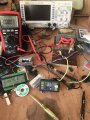
I was probing at the taps with the dmm and applying a current at the ends of the cable. That way I would get the resistance at the taps and the dmm reads 0.03mV

Does that help or make sense here ?
image.jpg
 

strantor

Joined Oct 3, 2010
6,875
Have you put your DMM in current mode in series to verify that your little current source is in fact outputting 0.999A? Those little cheap things can't be relied upon like a quality lab power supply.
 
Top