measure HIGH AC current with an Arduino

Thread Starter

anishkgt

Joined Mar 21, 2017
549
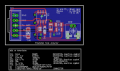
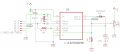
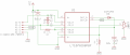
If the welder doesn't actually put out 3500A exactly maximum (more or less) then you might need to adjust R3. if the shunt value isn't actually 0.0001 ohms then you need to adjust R3
Ideally you would dial it in for 5V at max amps, not 3.5
Would be easier to do that if R3 was a pot.
How do we know the amount of gain to adjust, i mean as a reference to what ?
 

strantor

Joined Oct 3, 2010
6,875
How do we know the amount of gain to adjust, i mean as a reference to what ?
I would connect the circuit across a section of weld lead as discussed, short the welding leads, and turn on the power to the transformer, so that your transformer is putting out max amps. Then while it is on, adjust the pot so that you get 5V (or 4V, or whatever the max opamp output is). That way you know that your max opamp voltage output corresponds to your max transformer current output. Then you can can scale the analog input of the arduino via software to read out in actual amps.

NOTE: Try to make your adjustment as fast as possible to avoid burning up your transformer.
 

Thread Starter

anishkgt

Joined Mar 21, 2017
549
I would connect the circuit across a section of weld lead as discussed, short the welding leads, and turn on the power to the transformer, so that your transformer is putting out max amps. Then while it is on, adjust the pot so that you get 5V (or 4V, or whatever the max opamp output is). That way you know that your max opamp voltage output corresponds to your max transformer current output. Then you can can scale the analog input of the arduino via software to read out in actual amps.

NOTE: Try to make your adjustment as fast as possible to avoid burning up your transformer.
Hmmm ok. So that would give the max voltage the opamp read for max amps of the transformer. In other words calibrating the opamp with the cable and the transformer. So a switch on time of 500ms would be enough i guess will have to test that and see how that goes.

Thank you for that. You should have youtube channel for teaching basics.:)
 

strantor

Joined Oct 3, 2010
6,875
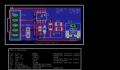
your pot is going between +5V and gnd. In the last schematic you posted, it was between R24 (eagle layout) and Isense (eagly layout). I do not understand the way you have it there, hope it was intentional.
 

Thread Starter

anishkgt

Joined Mar 21, 2017
549
So what is the use of R24 here ? without it and C19 gives same voltage 4.2v.

sorry for the silly questions just clearing doubts.
 

strantor

Joined Oct 3, 2010
6,875
R24 combined with the pot forms a voltage divider to set the opamp gain. Im not sure why you get the same output Without it but I theorize without it your gain is fixed since no divider.
 

Thread Starter

anishkgt

Joined Mar 21, 2017
549
well i got a bit lost with working on it.

I've measured the transformers secondary resistance with the Kelvin technique and it reads 0.00537Ω.

Calculation
V = 0.0067v (probing 13cm apart on the cable with a DMM) for 60ms pulse
R = 0.00537Ω
I = V/R
= 1,247Aamps
 

strantor

Joined Oct 3, 2010
6,875
well i got a bit lost with working on it.

I've measured the transformers secondary resistance with the Kelvin technique and it reads 0.00537Ω.

Calculation
V = 0.0067v (probing 13cm apart on the cable with a DMM) for 60ms pulse
R = 0.00537Ω
I = V/R
= 1,247Aamps
the value of 0.00537Ω is that across the 13cm section?
 

Thread Starter

anishkgt

Joined Mar 21, 2017
549
the value of 0.00537Ω is that across the 13cm section?
That was the whole wire length, end to end. Shouldn't that be the way to measure it. I mean the section is just to take the voltage reading or should Viltage reading also take from the electrode itself.
 

strantor

Joined Oct 3, 2010
6,875
Just a thought, how would it differ when sensing at both electrodes and resistance of the end to end cable.
dude....

.....

...

again with the open circuit voltage thing....

Please review our prior conversation(s) about this. I don't know what else to say about it.
If you still don't understand then please just take my word for it.
Resistance of your 13cm cable section (not the entire secondary) is what you need to know.
Voltage dropped across that resistance (of the 13cm section of cable) is what indicates amperage through the cable.

Sorry if I'm being rude but I thought we were past this.
 

dendad

Joined Feb 20, 2016
4,641
I take it you are asking about measuring the voltage across the electrodes to work out the current.
You only need to measure the voltage across a short length of one cable to work out the current. A longer length will give you more voltage to play with so you may not need an amplifier to get enough volts to measure. You are measuring the voltage across a resistor in series with the load to work out the current. A longer part of the lead is a higher resistance.
Measuring across the full length is ok, as long as you use Kelvin connections so as not to add the voltage drop of the terminals to your reading.
BUT if you measure across the electrodes, the measurement will be your supply voltage not the current when the electrodes are open, and the voltage across the joint being welded when closed. And as the weld joint is an unknown highly variable value, it is useless for calculating the current.
Current measurement needs to be taken from ONE wire only. There is no point on connecting to both wires as the current will be the same in the series circuit but if you take your measurement across both wires it will be meaningless.
I suppose you could measure the volts at the transformer end, then subtract the volts measured at the electrode end then using the difference, work out the current but why do it that way? Just the voltage drop across a sample of one cable is all you need and the easiest way to do it.
 
Last edited:

Thread Starter

anishkgt

Joined Mar 21, 2017
549
Ok so I did as you said and the resistance at the cross section is 0.002Ω and the voltage at the cross section during a weld is 0.0030V for 60ms

So doing the math would be
I = 0.003/0.002
= 1.5A

Really ?
 
Top