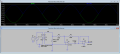
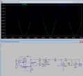
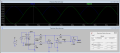
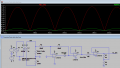
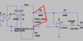
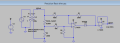
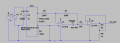
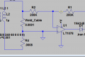
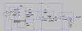
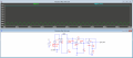
Current in weld circuit: 3500A
Voltage drop across weld_cable (section of weld lead): 350mV
350mV amplified to 3.5V by U3
3.5V then rectified by U1 & U2
The challenge is that we are trying to measure a difference in a floating circuit. There is no ground there, so a difference amplifier is what is typically prescribed. Difference amplifier needs a negative supply. But since the transformer secondary is isolated, then maybe it would be ok to ground part of it to the measurement circui in order to eliminate the need for a difference amp. I'm not sure I'm being clear. I will play with it some more later tonight. I am not at my PC now.
Ok man I think I got it. Grounded a point in the weld circuit and sent the ~350mV to the rectifier, then out of the rectifier into a gain 10 non-inverting amp. No more need for dual supplies.
I'm not sure what's going on here but U3 isn't doing anything with its output tied like that, and I think you're back to measuring 3+ volts directly due to your ground point and ideal transformer.
Well i looked up U3 and added a resistor to gnd from the Non-inverting input to gnd. If this isn't the one then i guess i'll just leave my design as is and move on.
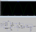
Look at the difference in the waveform between the circuit I posted in post #47, and the circuit you posted in #49. In post #47 a 350mV AC signal is transformed into a 3.5V rectified signal. In post #49, a 3.5V AC signal is transformed into a 3.5V rectified signal.
You should consider it a red flag if your initial original signal is more than millivolts. Because of the "perfect" (ideal) simulation transformer, and because of where you grounded the secondary, your simulation leads you to believe this works, but it doesn't You're once again, effectively measuring "open circuit voltage."
There's no need to give up. In post #47 I provided what I believe to be a perfectly workable solution. I plan in fact to implement that very circuit on my own spot welder when I get back around to making REV2 of that project.
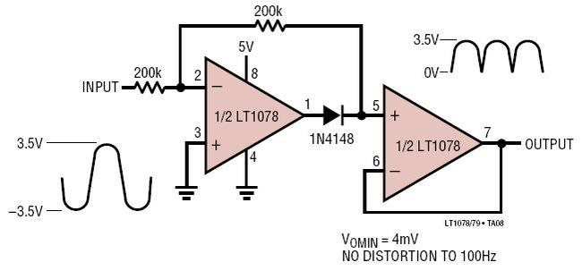
Isn't that how the 'Precision full wave voltage rectifier' designed to work as per the LT article.The main design of the circuit was to get the same output voltage as the ac signal.
I was using that as a reference in the design and the third opamp U3 was something i was just following your advise.
Isn't that how the 'Precision full wave voltage rectifier' designed to work as per the LT article.The main design of the circuit was to get the same output voltage as the ac signal.
I was using that as a reference in the design and the third opamp U3 was something i was just following your advise.
Yes, The LT article describes a circuit that takes a 3.5VAC signal and turns it into a 3.5V rectified signal.
The problem is that placing a low value shunt in the high current circuit cannot possibly give you a full 3.5VAC signal to rectify. It can only give you millivolts.
You have been trying to make your circuit give a 3.5VAC signal to match the LT article. You have succeeded in simulation but in real life you will not see that.
We need the circuit to do something more than simply rectify, as the LT article describes. We need it to rectify, and amplify.
Actually in the course of writing that last sentence I have realized another obvious thing that I missed.
That 2nd opamp (on the right) in the LT article is an amplifier with a gain of 1.
We need one with a gain of 10. That's the 3rd opamp in my circuit. But we can simplify by giving the original opamp a gain of 10, and getting rid of the 3rd opamp.
(circuit uploaded)
I really feel like I'm not explaining this very well and I'm sorry for that.
I will try to explain in more detail and hope I don't confuse you further...
When you measure a voltage in LTSpice, it is assumed you are measuring from the common ground point - assume you have your black DMM probe clipped to the little triangles.
So when you click to measure the voltage at the left side of your 168k resistor R3, you are effectively measuring directly across the transformer secondary - the entire source voltage:
And when you do that, you get an AC waveform of 3.5V.
Does that seem right to you?
You have a transformer putting out 3,500+ Amps through a combined resistance of 0.0009 Ohms, and his output is still a full 3.5V, as if he were unloaded?
That does not seem right to me. It is not right.
I have run my spot welder to that many amps, and the voltage drops practically to nothing, less than 1VAC.
This is what I mean when I talk about the "perfect" or "ideal" transformer in simulation. The transformer does not behave as a real life transformer should; his voltage does not drop.
So your circuit, which is based on having a 3.5V input, is not going to work.
This is why I stress that we measure across a known resistance, a "shunt", which is simply a section of the welding lead.
The voltage drop across a known shunt resistance will give a very accurate amp reading, no matter whether the transformer output drops to 2V, or 1.5V, or 0.2V, or whatever, it doesn't matter.
As long as you design for that millivolt signal, your transformer can drop to whatever voltage it feels like, and you'll still have accurate amp reading; that's why I said that inputting the impedence of the transformer into sim doesn't matter now - because we're only (supposed to be) looking at that millivolt drop across "weld_cable"
Now look at the difference between where my ground point is, and where your ground point is. Here's mine, and see that I'm only looking at the voltage drop across that shunt, not the entire output of the secondary winding:
See how instead of grounding it at the bottom of the screen, I grounded it between the two resistors? this means I only measure across the shunt. And this gives me the millivolts signal that I need.
I hope all that makes sense. I am not the best at explaining things.
Yes your explanation does make a lot of sense, really makes a lot of sense. yes its obviously in millivolts that the measure should go into the opA and i can't believe i've been doing the same mistake over and over again.
Sorry if i made you loose your time over this but your a good teacher.
would it be ok to have a common gnd at the non-inverting pin of U1, the voltage is zero at gnd. Does give the same result. Don't want to assume like i did earlier. If this circuit would be confirmed then i can get back to Eagle and design it.
Tip:
To probe two nodes just click the probe and drag to next node, also right clicking would all to 'mark a reference'
"If one can't explain things in the simplest form then one has not understood it very well".
-Unknown Author
Yes your explanation does make a lot of sense, really makes a lot of sense. yes its obviously in millivolts that the measure should go into the opA and i can't believe i've been doing the same mistake over and over again.
Sorry if i made you loose your time over this but your a good teacher.
would it be ok to have a common gnd at the non-inverting pin of U1, the voltage is zero at gnd. Does give the same result. Don't want to assume like i did earlier. If this circuit would be confirmed then i can get back to Eagle and design it.
Yes, that is fine. That's actually how it is already. The little ground triangles indicate that ground. Meaning, any time you see a ground triangle, it is connected to all other ground triangles. We use the triangles to simplify the drawing. This is the exact same circuit, with wires drawn instead of ground triangles:
NOTE: it is the same for the +V net.
You can create your own "nets" in LTSpice and name them whatever you want. Then instead of drawing wires all over, you can specify a net, and simplify your drawing. In our drawing, we called the positive output of the 5V source "+V".
Here I have deleted the net and replaced with wires as an example. Circuit is exactly same as before.
NOTE 2:
The only reason why we grounded the transformer primary winding is because LTSpice will generate an error for any ungrounded circuits. That's stupid, and irritating. A bad thing about LTSpice. In real life there is no need or reason to ground the transformer primary.
The only reason why we grounded the transformer primary winding is because LTSpice will generate an error for any ungrounded circuits. That's stupid, and irritating. A bad thing about LTSpice. In real life there is no need or reason to ground the transformer primary.
OK one last bit of input before making the board...
R3 in my circuit (9k resistor). I would make this a potentiometer actually, so that you can adjust the output gain. 0-20kOhm would be good
Currently our circuit gives 3.5V rectified for 3500A.
If the welder doesn't actually put out 3500A exactly maximum (more or less) then you might need to adjust R3. if the shunt value isn't actually 0.0001 ohms then you need to adjust R3
Ideally you would dial it in for 5V at max amps, not 3.5
Would be easier to do that if R3 was a pot.
Would be best if the op amps power supply was more than 5V.
5V is what came from the original circuit from LTSpice website, and we just stayed with that value.
it should be about 10V or so (max 22V)
I assume you are using something higher than 5V for the arduino, so maybe just use that.
if not; if all you have is 5V then that's probably still fine, just don't expect to get 5V out of an opamp who's supply is only 5V. They only go within a limit less than supply voltage.
if only 5V is available then maybe scale in the arduino for max @ 4V.
If the welder doesn't actually put out 3500A exactly maximum (more or less) then you might need to adjust R3. if the shunt value isn't actually 0.0001 ohms then you need to adjust R3
Ideally you would dial it in for 5V at max amps, not 3.5
Would be easier to do that if R3 was a pot.
Would be best if the op amps power supply was more than 5V.
5V is what came from the original circuit from LTSpice website, and we just stayed with that value.
it should be about 10V or so (max 22V)
I assume you are using something higher than 5V for the arduino, so maybe just use that.
if not; if all you have is 5V then that's probably still fine, just don't expect to get 5V out of an opamp who's supply is only 5V. They only go within a limit less than supply voltage.
if only 5V is available then maybe scale in the arduino for max @ 4V.
Not really, the arduino is powered by a 5v power source. Why would you need 10v ?
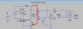
Meanwhile i was watching this tutorial done by Dave of EEVblog. Seems to be the same thing we had been doing hence i've eliminated a few resistors and matched the out to be dc rather having the MCU do the job of sampling and rubbish. Either way the aim was to get the peak value so a full wave rectifier is not necessary.

 Facebook
 Google
 GitHub
 Linkedin