Facebook
 Google
 GitHub
 Linkedin
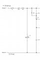
My current lathe controller does have encoder feedback, so I'll have to look into it's settings to figure out the low rpm fluctuations. I always just assumed it was the mc2100 causing it. Thank youImplementing some kind of feedback would help, although you would need to implement it yourself, the original TM fed the belt or motor sensor back to the console where it was processed, IOW, the MC2100 motor control board does not process it.
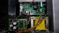
MC2100 treadmill motor control circuit
- Thread starter domingojordan
- Start date