Facebook
 Google
 GitHub
 Linkedin
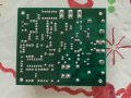
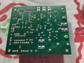
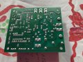
Hi everyone. I am having a problem with this MC-02 treadmill motor control board. In the treadmill it is not working. there is no power going to the motor terminals. Taking it out and testing it on the bench the motor starts up full speed with no control from the potentiometer?? I have tried searching in this thread with no results. Maybe someone here have seen this before and can help.
Attachments
-
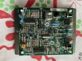 446.2 KB Views: 13