
LTspice simulation unexpected results and unable to simulate pulling a pin low with MOSFET

BobTPH

Joined Jun 5, 2013
11,618
Would that be more accurate than just using a voltage divider? What would the output of the comparator be connected to, my transistor base?
You don’t need the transistor if you use a comparator, the transistor is inside the comparator.

And yes, a comparator is far more accurate than a simple transistor. It is an entire circuit designed to accurately compare two voltages and switch when one exceeds the other.
 

Thread Starter

jim0000

Joined Oct 28, 2020
130
You don’t need the transistor if you use a comparator, the transistor is inside the comparator.

And yes, a comparator is far more accurate than a simple transistor. It is an entire circuit designed to accurately compare two voltages and switch when one exceeds the other.
The transistors main function is to add a short to ground once a certain voltage is reached in order to pull the EN/UVLO node (at the collector of transistor) low. I wasn't sure how to do that with a comparator?
 

BobTPH

Joined Jun 5, 2013
11,618
The transistors main function is to add a short to ground once a certain voltage is reached in order to pull the EN/UVLO node (at the collector of transistor) low. I wasn't sure how to do that with a comparator?
That is exactly the function of a comparator.
 

Papabravo

Joined Feb 24, 2006
22,105
Oh wow thank you for the info, I am having a hard time figuring out what this circuit is doing, is it pulling a GPIO pin lower with the comparator?
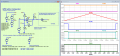
Yes, look at the signal traces. When the input V(Vin) exceeds the UTP (Upper Threshold Point) the output V(Vo) goes low. Note that "low" in this context is not the same as GROUND, but very close to it, 122 mV to be more precise. The output stays low until the input reaches the peak of +30 volts and starts to head back toward GROUND. When the input reaches the LTP (Lower Threshold Point) the output returns to the high state. This property is called hysteresis and it prevents the output from bouncing up and down in the vicinity of a single threshold point. It is a very useful property to use in this context.

Most comparators have this open collector(drain) configuration since they are effectively converting analog information to a single bit of digital information. The comparator with this type of output can work with a large variety of logic families. The pullup resistor is R1, and I have chosen a value of 332 Ω. If the value is too low, it will dissipate excessive current when the comparator output is low. In this case with a VCC=3.3VDC the current will be 3.3V/332 Ω ≈ 10 mA. If the resistor is too large, then the rise time of the signal going high will be longer.

The power dissipation in the output low state will be:

\( P_D\;=\;(10\text{ ma})^2\times332\;\Omega\;\approx\; 32\text{ miliwatts} \)

which can be easily handled by a typical SMT resistor
 
Last edited:

Thread Starter

jim0000

Joined Oct 28, 2020
130
Most comparators have this open collector(drain) configuration since they are effectively converting analog information to a single bit of digital information. The comparator with this type of output can work with a large variety of logic families. The pullup resistor is R1, and I have chosen a value of 332 Ω. If the value is too low, it will dissipate excessive current when the comparator output is low. In this case with a VCC=3.3VDC the current will be 3.3V/332 Ω ≈ 10 mA. If the resistor is too large, then the rise time of the signal going high will be longer.

The power dissipation in the output low state will be:

\( P_D\;=\;(10\text{ ma})^2\times332\;\Omega\;\approx\; 32\text{ miliwatts} \)

which can be easily handled by a typical SMT resistor
Okay thank you for the help I need it. I have an LM339 and LM324 on hand. Could the design readily use those or will modification be needed?
 

Papabravo

Joined Feb 24, 2006
22,105
Okay thank you for the help I need it. I have an LM339 and LM324 on hand. Could the design readily use those or will modification be needed?
The LM324 is an operational amplifier and not a comparator. You don't want to use that for this application.
As I noted on the simulation schematic the LM193, LM293, and LM393 are all the same part except for operating temperature range. These parts are dual parts because there are two comparators in each package. The LM139, LM239, and LM339 are the same comparator except they come with four comparators in each package. Please examine the datasheets to confirm this. You should ALWAYS get into the habit of reading datasheets to confirm each, and every claim made about a part.

One more thing. If you are only using one comparator in a package of four, make sure you do not leave the inputs of the unused comparators floating (unconnected). Tie them to something that will not allow the outputs to oscillate. In particular do not tie both inputs to the same potential
 

Thread Starter

jim0000

Joined Oct 28, 2020
130
The LM324 is an operational amplifier and not a comparator. You don't want to use that for this application.
As I noted on the simulation schematic the LM193, LM293, and LM393 are all the same part except for operating temperature range. These parts are dual parts because there are two comparators in each package. The LM139, LM239, and LM339 are the same comparator except they come with four comparators in each package. Please examine the datasheets to confirm this. You should ALWAYS get into the habit of reading datasheets to confirm each, and every claim made about a part.

One more thing. If you are only using one comparator in a package of four, make sure you do not leave the inputs of the unused comparators floating (unconnected). Tie them to something that will not allow the outputs to oscillate. In particular do not tie both inputs to the same potential
Oh okay thank you for that info I wouldn't have known that. Should all unused inputs of the LM339 for example be tied to ground?

Also for the voltage reference do you think an LM431 or LM1117 would be better?
 
Last edited:

Papabravo

Joined Feb 24, 2006
22,105
Oh okay thank you for that info I wouldn't have known that. Should all unused inputs of the LM339 for example be tied to ground?

Also for the voltage reference do you think an LM431 or LM1117 would be better?
If you connect both inputs of the comparator to the same potential, the output can oscillate. You want the opposite of that behavior.

A pair of 1% resistors is usually appropriate for a reference. Look at the schematic in post #23 and notice how the value of V(VTH) changes as a function of V(Vo) to provide two different reference values. If you consider just R2 & R3, what would the value of V(VTH) be? If it was me, I would connect the output to the non-inverting (+) input and connect the inverting (-) input to GROUND. This should turn off the output stage and the pullup resistor will hold the output and the non-inverting (+) input at VCC
 
Last edited:
Top





