Facebook
 Google
 GitHub
 Linkedin
Hi,
Hope everyone is doing great.
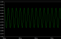
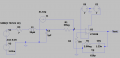
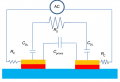
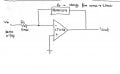
I am building a circuit in LTSpice using the inverting configuration of the LT1028 operational amplifier. The input signal provided is 0.7 Vp, which is applied to R1 (5M ohm). For the feedback resistor (Rf), I am using my biosensor, whose impedance varies from 10M ohm to 25M ohm. The equivalent circuit of my biosensor is attached in the picture. I want to measure the value of Rf using the formula:
Rf= R1 x ( −Vout/Vin)
After R1, the voltage drops from 0.7 Vp to 60 uV before reaching Rf (the biosensor).
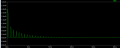
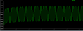
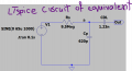
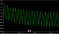
I have created a separate circuit in LTSpice representing the equivalent circuit of my biosensor. The values I used for R and C in this LTSpice circuit are based on the impedance analyzer readings. The actual impedance of my sensor is 15M ohms, but I used the values of R and C provided by the impedance analyzer, where R and C are in parallel. The voltage applied to this circuit is 60 uV, but the output I obtained from the circuit is very low (around 0.8 uV), and the waveform after the circuit is not a sine wave.
Given this, the impedance value for Rf that I calculated is incorrect.
I have a few questions:
Hope everyone is doing great.
I am building a circuit in LTSpice using the inverting configuration of the LT1028 operational amplifier. The input signal provided is 0.7 Vp, which is applied to R1 (5M ohm). For the feedback resistor (Rf), I am using my biosensor, whose impedance varies from 10M ohm to 25M ohm. The equivalent circuit of my biosensor is attached in the picture. I want to measure the value of Rf using the formula:
Rf= R1 x ( −Vout/Vin)
After R1, the voltage drops from 0.7 Vp to 60 uV before reaching Rf (the biosensor).
I have created a separate circuit in LTSpice representing the equivalent circuit of my biosensor. The values I used for R and C in this LTSpice circuit are based on the impedance analyzer readings. The actual impedance of my sensor is 15M ohms, but I used the values of R and C provided by the impedance analyzer, where R and C are in parallel. The voltage applied to this circuit is 60 uV, but the output I obtained from the circuit is very low (around 0.8 uV), and the waveform after the circuit is not a sine wave.
Given this, the impedance value for Rf that I calculated is incorrect.
I have a few questions:
- Did I correctly build the equivalent circuit of my biosensor in LTSpice? If not, could someone suggest the necessary changes to the circuit?
- Why am I not getting the correct value for Rf when I use the equivalent LTSpice model? When I use a simple resistor for Rf, I can calculate the correct value using the above formula.
- Can someone explain why the LTSpice model of my equivalent circuit alters Vout and why the parallel capacitor significantly affects Vout?
Attachments
-
2.2 KB Views: 3
-
 48.5 KB Views: 6
 -
824 bytes Views: 3
-
 25.8 KB Views: 6
 -
 33.1 KB Views: 6
 -
 22.5 KB Views: 5