Facebook
 Google
 GitHub
 Linkedin
Hello all,
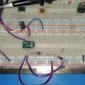
I am attempting to recreate this circuit:
https://www.eevblog.com/forum/projects/need-a-small-accurate-100hz-oscillator/25/
Not getting any output, If I wite The SET pin to V+, then I get 125Khz output.
I need the set in to be on ground.
I looked up the datasheet , recreated the last circuit on page 19 and still nothing, and again I get 35Khz out if I put set to 5V.
anyone having this issue?
Ken