 Facebook
 Google
 GitHub
 Linkedin
Hi,
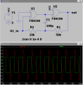
I've simulated the attached circuit and noticed it violates the absolute maximum input rating of -0.5V to Vcc + 0.5V. I've seen this circuit with a CD4070 which has similar maximum ratings but I have a 74HC86 and so thought I might use that.
Will this oscillator self-destruct or is it fine somehow?
I've simulated the attached circuit and noticed it violates the absolute maximum input rating of -0.5V to Vcc + 0.5V. I've seen this circuit with a CD4070 which has similar maximum ratings but I have a 74HC86 and so thought I might use that.
Will this oscillator self-destruct or is it fine somehow?
Attachments
-
 49.8 KB Views: 65
 -
989 bytes Views: 7


