You could use an LM338 which operates the same as an LM317 with a 1.2V-32V output range, but has a maximum current rating of 5A.
The main concern will be the size heat sink to handle its power dissipation.
You could use an LM338 which operates the same as an LM317 with a 1.2V-32V output range, but has a maximum current rating of 5A.
The main concern will be the size heat sink to handle its power dissipation.
Nice, I didn't know the LM338 existed. For a solution with LM317 I'm thinking, how about a PNP power transistor turned on in parallel with an LM317 by a small resistor in the line between 40V and the LM317 with a drop of say 0.6V and above helping the transistor to take most of the current. But the LM338 is simpler and without checking I'm not sure if my idea works! As you say, the problem with this and any other linear power supply is getting rid of the lost power I x (Vin - Vout). Hence the benefit of switching supplies. Easy enough to design switching supplies with known input and output voltage, harder if the output voltage is required to vary over a wide range for a bench top power supply.
For a solution with LM317 I'm thinking, how about a PNP power transistor turned on in parallel with an LM317 by a small resistor in the line between 40V and the LM317 with a drop of say 0.6V and above helping the transistor to take most of the current.
The PNP wrap around transistor trick is a classic that has been used for a lot of years. It has been approved by experts and included in many trustworthy publications.
The only inconvenience is that it is not also a current regulator. It is strictly a voltage regulator circuit.
The PNP wrap around transistor trick is a classic that has been used for a lot of years. It has been approved by experts and included in many trustworthy publications.
True.
But unless you already have the LM317 and associated parts for the boost transistor, I see no reason to do that over using the LM338.
The LM338 circuit is much simpler, and has the added advantage of providing full safe-area, current-limit, and over-temperature protection.
Here I added a little 10V wall wort cell phone charger to power the op-amp. Did not add current limit yet.
Could not get the TL431 to work so I used 3.3V zeners. 1mA passes through R1, 10, 11. Set the value of voltage by R11 (pot) 20k ohms for 20 volts.
No high voltage on the op-amp. Use any general purpose amp.
First go at it so there are probably problems. lol
RonSimpson
hello, thank you for all the suggestions, though my knowledge in electronic is not as broad as yours, im willing to learn based on your comments. for the meant time i will use a zener to regulate the voltage from 40v to maybe lower like 30v for the lm358 vcc
Hi muno,
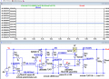
This is what LTS shows with a 12V Zener from the +40Vs, the LM358 is powered from +28V.
[circuit includes also the last modifications posted, ie: 7k and 2k7 resistor changes]
Note the power dissipation in the TIP power transistor.
E
Added a 2nd image showing Node voltages, when set for 25V at 3A
May be helpful in debugging your built circuit.
Hi muno,
This is what LTS shows with a 12V Zener from the +40Vs, the LM358 is powered from +28V.
[circuit includes also the last modifications posted, ie: 7k and 2k7 resistor changes]
Note the power dissipation in the TIP power transistor.
E
Added a 2nd image showing Node voltages, when set for 25V at 3A
May be helpful in debugging your built circuit.
thank ypu for this, i really appreciate it, i will gather all the parts needed for the circuit, anyway, are those caps polarized? and what are they voltage ratings? i have also seen in the comments that adding a series diode in d1 and d2 will give more voltage? and that d3 doesnt need a resistor from 40v line?
hi m,
Use electrolytic caps, rated at 50Vdc.
Let us know what you plan to do regarding the heat sink for the TIP.
Note: the circuit assumes a smoothed +40Vdc input, rated at say 4 Amps, not a rectified bridge output.
Ref the extra diodes, ask the posters who referenced the diodes.
E
BTW: Across the 1000uF I would add a 100nF cap, will help in electrical noise reduction,.
thanks. i will be using big heatsink with fan for the tip transistor. the 40vdc will be coming from a bridge rectifier with 50v 4700uf cap. another thing, is that zener doesnt have any resistor before it? is it directly connected to 40v line, maybe i will burn that zener(d3)?
hi muno.
Please post details of the bridge rectifier.
If the transformer is rated at say 50Vac , that means 50Vac, RMS, when rectified and smoothed, could be in the order of 70Vdc output. !!
im wrong in my computation so there will be atleast 35VDC at the filter cap(after bridge rectifier), 28VAC * 1.41 = 39.48VDC - 10% = 35.532VDC at the filter cap?
hi muno..
How will connect the bridge rectifier to the centre tapped 28v-0v-28v transformer.?
E
I will draw up a sim to see the result.
Update: I see the rectifier you are going to use is a single Schottky diode, so I expect one pair of diodes on each of 28V transformer ends, making a Bridge.
 Facebook
 Google
 GitHub
 Linkedin