Inductance meter with LM311 or LM358

Thread Starter

pekka123

Joined May 18, 2017
40
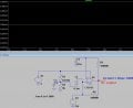
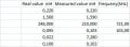
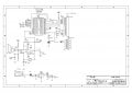
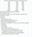
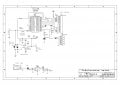
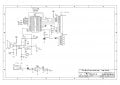
Hey. I am doing an inductance meter with PIC18F2620, but it is not important. The analog comparator or amplifier is. I have tried first with LM311. It is a comparatori. It works almost well, but not perfectly. It makes a small high-frequency oscillation with a normal lower frequency. It works with high inductance, but not a small onces, The limit is about 0.1mH. Then I changed to LM358 dual operational amplifier, but it works much lower frequency, and all the frequencies were quite low. With 0.1mH it showed 1417mH, 0.022 mH it showed 1423mH and with 249mH incuctamce it showed 1492 mH. What I have done wrong? Can somebody show me a link with LM358 inductance meter?
 

Attachments

Ian0

Joined Aug 7, 2020
13,097
How is it meant to work? This is with a MCP6071 op-amp. It oscillates around 800Hz, but the value depends on C2/R3/R4 and not on the inductance.Screenshot from 2025-08-02 21-29-12.png
 

MisterBill2

Joined Jan 23, 2018
27,164
The LM311 is a quite good comparator, and it is optimized for comparator applications. The LM358 is a mature opamp, and has been around for a few decades. There are many opamps now available with much better performance in every aspect.
I suggest creating a list of requirements for the op-amp and going to the Analog Devices website
 

0ri0n

Joined Jan 7, 2025
160
Limit the max. oscillation frequency by using some additional series inductance (L1 = 100uH for fmax = 500kHz). The actual DUT (LX) will then be in series with L1. Works with LX = 0nH ... 1H, at least in simulation. As the values of L1/C1 are de facto not precisely known, switch in temporarily a second, tight tolerance cap of known value in parallel to C1 to be able to calculate L1/C1 during the calibration phase.

Oscillator_L-Meter.png
 

Thread Starter

pekka123

Joined May 18, 2017
40
Thank you for all. I have tried to do this comparator meter many times, but I have not got any signal with this connection. Häve you tried to test it with real components? I tried today using LTSimulator and with LM358, but LTSimulator doesn't know LM358, I used a similar LT1013 , but I didn't get any signal. I tried to change the components, but did not succeed. Can somebody to get it working, I real life, it works 464Hz, which is too low for a 0.1mH inductor.I have tried to do working inductance meter theree months.
 

Attachments

MrChips

Joined Oct 2, 2009
34,628
LM311 and many comparators have open-collector output.
You need a pullup load resistor to Vcc at the output pin.
 

ericgibbs

Joined Jan 29, 2010
21,390
hi pekka,
This is what LTSpice shows with a LM311 for that d/s circuit.
Where is R9 [ on the PDF] on your asc circuit??? R4 on my sim.....

E
EG 1661.png
 

Thread Starter

pekka123

Joined May 18, 2017
40
These are real results with my test circuit. It uses LM311. But when the inductance goes smaller, it will generate a fast frequency, which affects the results, I use PIC18F2620 with 8MHz intenal clock. It will go to LCD, but now it is only serial output,
 

Attachments

ericgibbs

Joined Jan 29, 2010
21,390
But when the inductance goes smaller, it will generate a fast frequency,
Hi pekka,
Please post some actual inductance/frequency values and what the results effect shows

Is your LTSpice simulation now working?

E
 

Thread Starter

pekka123

Joined May 18, 2017
40
I put the real values of my measurements with PIC18F2620 8MHz internal clock. It also has my test code with CCS c- compiler v. 5.12, Note that it has no interrupts. It only measures 0.1s, the frequency that goes to PIN_C0, input for the timer1.
 

Attachments

Thread Starter

pekka123

Joined May 18, 2017
40
I tried to operate my simulator, I tried to differentiate resistors, I tried to add a small startup voltage, but I didn't get any oscillation. My real LM358 device oscillated, but it had two low oscillations. It was different the my comparator LM311.
 

MisterBill2

Joined Jan 23, 2018
27,164
Go to the ANALOG DEVICES website and get the simulator model of one of the high frequency opamps. Get one that is good for at least 50 megahertz! Use that model in the simulation. Itshould make quite a difference.
 

Thread Starter

pekka123

Joined May 18, 2017
40
OK, I'll try to do the real test circuit. Now I try to do PWM with 7.8k, 1.96 kHz, and 480 Hz. I try to output the signal from PIN_C2 to a 100R resistor and test the inductance in series. Then I connect the signal from the inductance to the op-amp, which has two diodes in opposite directions to a 1k resistor to ground. I put the - input of the opamp to the inductance and two diodes and + input to the other side of the diodes. From the output of the op-amp, I put a 10k series resistor and a 0.1uF capacitor to ground. So I try to see how much AC voltages I got from different inductors. Has anybody tried this connection? I will send a schematic when I am ready.
 

Thread Starter

pekka123

Joined May 18, 2017
40
This is my new inductance meter. I have tested it with 100uH and 1.63 mH inductors. It still has quite a bit of work to do the right software. I start with 100kHz and if the ADC is more than 4V, I decrease the frequency frecuency/2 , I the voltage is lower than 1 V I increase the frequency by 2*frequency.
 

Attachments

Top