Does it work? I hope it works, but I get confused about comparator inputs. You might have to reverse the inputs on the comparator to get this to work correctly.
What transistors to use here? It's simple transistors?
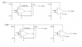
But here is compare two signals, first when is geting no - inverter and second is inverter.
Do I well understand?
Let's back up a second and talk about what your goals are. Are you sure you want a result that is either 0V or 3.3V? Your first post used the word "measurement" and to me that implies some proportional response, not off or on.
Did you add the bypass capacitor and stabilize the unused side of your op-amp?
In #17 your data suggests your detector is working, but not producing the output voltages you want. Is that right? You could use the unused side of your op-amp to change that output. I think the LM358 can get close to ground, and with a 7V supply will be able to produce a 3.3V output.
No you don't understand me. I would like to measure solar intensity but I want to get result between this voltage interval. Actually I make the sun tracker system but I want to use led generation signal, but I need to amplify signal because it's the signal is very weak for ADC. Actually I still not add the capacitor and stabilize. Currently I don't have the stabilize... Yes you are right I got some the signal but it works bad because I'm getting non-zero volt when is night.
So you want to squeeze the range from dark to full sun into the voltage range of 0 to 3.3V, right? If so, then forget the comparator.
You might want to look at an op-amp circuit known as an "instrumentation amplifier". It's commonly used to provide offset and scaling, zero and span, for a sensor. It's more complicated than your simple circuit, which should work for you, but does offer advantages.
Yes, you are right. Thank's for your help I think I did it and it's works a well. If you intersting I can add the video how to work.
I use the LM358 op-amp.
I'd recommend a transimpedance amp followed by a comparator. You can make a comparator with an opamp without feedback, so you can use a dual (or quad) opamp IC to build both the TIA and comparator. The current generated by a photodetector (not an LED, by the way) is proportional to the incident light intensity. With a TIA and comparator you can set the threshold very accurately. The threshold of your voltage mode circuit with the photodiode going to the + input of the opamp will vary with the offset voltage and current of the opamp, and so with temperature and supply voltage, etc.
I'd recommend a transimpedance amp followed by a comparator. You can make a comparator with an opamp without feedback, so you can use a dual (or quad) opamp IC to build both the TIA and comparator. The current generated by a photodetector (not an LED, by the way) is proportional to the incident light intensity. With a TIA and comparator you can set the threshold very accurately. The threshold of your voltage mode circuit with the photodiode going to the + input of the opamp will vary with the offset voltage and current of the opamp, and so with temperature and supply voltage, etc.
Do you can draw the schematic where you spoke about it with all component name and all nominals? I really interesting it and I will be grateful for it.
 Facebook
 Google
 GitHub
 Linkedin
 21 KB Views: 45


