LM358 operating amlifier & Led

Thread Starter

Ignas

Joined Sep 22, 2014
17
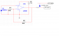
Hello everybody. I have question about light measurement. I have project where I need to measurement light signal using Led sensor. I need to get light voltage of the output signal between 0 V and 3.3 V. So I chose this interval because I will use ADC converter which to have atmega32, so I don't use more voltage interval because I would like to protect controller input from high voltage signal. So I using LM358 operational amplifier and when I simulation with multisim it's working think but when I connect in a real environment is not work and I don't know why is not work. Someone know about this and can help me.
upload_2014-9-22_18-37-47.png
 

#12

Joined Nov 30, 2010
18,224
The LM358 isn't designed for inputs within 1.5 volts of its supplies. Here's a chip that I saw yesterday. Look at the differences in input voltage range.
 

Attachments

Thread Starter

Ignas

Joined Sep 22, 2014
17
Emm... Where do you saw that input is 1.5 V? I offered to use this Amplifier. Every time I change amplifier but it's always not work. And It's very important me to know which circuit is need to use.
 

#12

Joined Nov 30, 2010
18,224
What is a 02BZ2.2?

From the look of that circuit, it is a Schottky diode with no current applied to it.

It looks like I read that wrong. The LM358 will accept inputs down to zero volts.
 

Attachments

Last edited:

Thread Starter

Ignas

Joined Sep 22, 2014
17
I posted it for only that looking circuit, so actually I using simple Led. Just ignore it.
I working reall envirument with a simple led.
 

#12

Joined Nov 30, 2010
18,224
So, will the LED produce a voltage of about .943 that can be amplified to 3.3 volts by:

.943 x (1 +5/2) =
.943 x 3.5 = 3.3005V?
 

wayneh

Joined Sep 9, 2010
17,498
Bypass cap on the power supply? Other op-amp in package is stabilized? How long are the leads on the LED "sensor"? This configuration would be very sensitive to noise on the LED.

Maybe post a photo of your build, and define what you mean by "it not work". What do you observe?
 

#12

Joined Nov 30, 2010
18,224
Good point wayneh. Some sort of frequency limiting is in order here. Either on the input side or a capacitor in the feedback loop.
 

wmodavis

Joined Oct 23, 2010
739
You might also look at using a transimpedance amplifier as used in some sun photometer instruments. Here is a link that provides some background and perhaps some information you may find useful. See particularly 4.2 Aerosols (Sun Photometer) and fig 20.
http://www.instesre.org/papers/UsingTheSun/using.htm#instruments
I presume you are interested in visible light measurement. The photometer referenced in the article has two photo sensors, one for green light and the other for red, that are within the visible spectrum.
 

Thread Starter

Ignas

Joined Sep 22, 2014
17
Bypass cap on the power supply? Other op-amp in package is stabilized? How long are the leads on the LED "sensor"? This configuration would be very sensitive to noise on the LED.

Maybe post a photo of your build, and define what you mean by "it not work". What do you observe?
I not sure for bypass what you are have mean? Yes I think it's stable. Leads is very short. I understand that is very sensitive to noise but I don't get output signal and I don't understand why. So I add my circuit picture.
 

Attachments

Thread Starter

Ignas

Joined Sep 22, 2014
17
In theory, that circuit will work, but I would add a protection diode to the output.
Other than that, we must look to your assembly skills.
But I need to get output signals now is 0 V. Zener diode protection between 0 to 3.3V.
 
Last edited:

wayneh

Joined Sep 9, 2010
17,498
Your IC is inserted wrong. Turn it 180°.

The power hookups also need to fixed. Check and double check the pinout.

OK maybe just V+ needs to be corrected. Anyway, check the pinout.

A bypass capacitor, for instance 0.1µF ceramic, is placed across the power pins. The unused op-amp should be stabilized. The data sheet should address the best way to do that. Or see here or here or here.
 
Last edited:

Thread Starter

Ignas

Joined Sep 22, 2014
17
You might also look at using a transimpedance amplifier as used in some sun photometer instruments. Here is a link that provides some background and perhaps some information you may find useful. See particularly 4.2 Aerosols (Sun Photometer) and fig 20.
http://www.instesre.org/papers/UsingTheSun/using.htm#instruments
I presume you are interested in visible light measurement. The photometer referenced in the article has two photo sensors, one for green light and the other for red, that are within the visible spectrum.
Thank for posted I will read about it. It's very interesting for me now. :)
 

Thread Starter

Ignas

Joined Sep 22, 2014
17
Your IC is inserted wrong. Turn it 180°.

The power hookups also need to fixed. Check and double check the pinout.

OK maybe just V+ needs to be corrected. Anyway, check the pinout.

A bypass capacitor, for instance 0.1µF ceramic, is placed across the power pins. The unused op-amp should be stabilized. The data sheet should address the best way to do that.
Yes It was wrong I don't connect supply pin...Is so Stupid mistakes. :/ Currently is not sensitive for light or dark.
My supply is about 7 V. When is dark I get output signal about 3.5 V and light when I turn on the lamp is 4.4 V.
I need get 0 V when is dark. :( And light 3.3 V. :(
 
Top