Facebook
 Google
 GitHub
 Linkedin
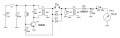
Thanks for suggestion.A little while back I was experimenting with an LT1361 dual op-amp with a 50MHz bandwidth.
Those Opamps require +/- 2.5V or higher supply. As i said , a 2.4V battery is to be used to power up the device
LT1361 - Dual and Quad 50MHz, 800V/µs Op Amps (analog.com)