linear actuator controller

Thread Starter

Xjsport95

Joined May 8, 2016
11
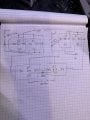
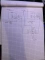
Im a little rusty, Ive been tinker for a few days but, having a hell of a time getting it to work... I have a linear actuator on the gate of my truck and nc limit switches... Im trying to get a latching relay to lock with a positive signal to run the actuator until it hits limit and shut off, next pulse reverse the direction and run until it limits, next pulse reverse again... any ideas? I've gotten it to work with a dpdt relay but, i don't like how it acts, has to be energized when the gate is closed.

Thankyou for any help
 

MisterBill2

Joined Jan 23, 2018
27,236
Instead of one button and alternating functions it will be much safer to have one button RAISEwhen it is pressed, and a second button lower when pressed, and halt when the button is released.
 

Thread Starter

Xjsport95

Joined May 8, 2016
11
Instead of one button and alternating functions it will be much safer to have one button RAISEwhen it is pressed, and a second button lower when pressed, and halt when the button is released.
Plan on using the fob to open with a trunk pop signal… or a single button at the tailgate
 

MisterBill2

Joined Jan 23, 2018
27,236
OK, now we have "trunk pop signal" and a lift gate on a truck. A bit confusing to me. The momentary pulse to start the action demands a means to know which action is required, raise or lower. AND, without some means to halt the action, the system is unsafe.
The scheme to use two SPDT relays has been posted many times on this site and it only requires one relay to be active to drive the motion. A latched-on scheme will be a poor choice because it is unsafe.
 

Thread Starter

Xjsport95

Joined May 8, 2016
11
OK, now we have "trunk pop signal" and a lift gate on a truck. A bit confusing to me. The momentary pulse to start the action demands a means to know which action is required, raise or lower. AND, without some means to halt the action, the system is unsafe.
The scheme to use two SPDT relays has been posted many times on this site and it only requires one relay to be active to drive the motion. A latched-on scheme will be a poor choice because it is unsafe.
I have a fob from a sedan programed and theres a trunk button, I plan to use that channel. "pop signal" just a momentary pulse, or could us a latching relay until hits the limit switch, they would be sharing a ground so it could "unlatch" the relay
 

MisterBill2

Joined Jan 23, 2018
27,236
That circuit in post #7 gets confusing after the first move. I see that it shows a button for open and another for close. Or is that the same circuit showing that it has two conditions that alternat with button pushes?? CERTAINLY it is a challenge to create a control system using the standard automotive cube relays.
 

Thread Starter

Xjsport95

Joined May 8, 2016
11
That circuit in post #7 gets confusing after the first move. I see that it shows a button for open and another for close. Or is that the same circuit showing that it has two conditions that alternat with button pushes?? CERTAINLY it is a challenge to create a control system using the standard automotive cube relays.
single button with two connections... the first two relays are just latching, when it hits the opposing limit it cuts the ground turning it off, the opposite of the limit is the ones that's triggered when the pulse is hit next. the lower set is just a simple reversing when holding the button... if I drew it up right... wanted standard relays because it will be mounted in a tailgate, subject to vibrations, moisture...
 

MaxHeadRoom

Joined Jul 18, 2013
30,571
If it is the type of linear actuator, 2 wire, where the limits are built in with diodes in parralel and reverse by polarity change, this circuit may work for you.
The circuit is a relay flip-flop with single button, you may have to change the C & R for 12vdc. Also the relays for 12vdc
Also, if you require a power lockout in the event of power failure in order that the reverse does not occur on re-power up. a simple power e-stop circuit can be supplied.
 

Attachments

Last edited:

Thread Starter

Xjsport95

Joined May 8, 2016
11
If it is the type of linear actuator, 2 wire, where the limits are built in with diodes in parralel and reverse by polarity change, this circuit may work for you.
The circuit is a relay flip-flop with single button, you may have to change the C & R for 12vdc. Also the relays for 12vdc
Also, if you require a power lockout in the event of power failure in order that the reverse does not occur on re-power up. a simple power e-stop circuit can be supplied.
Ther two contacts controlling the actuator are the two spares on RLYA.
what kind of relays Are those? im a little lost, wheres the relays coil
 
Top