LINEAR, 12V, DC, PSU THAT WON’T WORK

Thread Starter

vfaucher

Joined Aug 31, 2016
4
I’ve just made a linear, 12V, DC, 5A, regulated power source to power up a 12V, 2.7A (35W) halogen lamp. The power source works, but the lamp is not lighting.

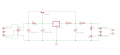
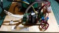
According to a schematic I copied from in the Web, I used a 12V voltage regulator (LM7812, TO-220) and a TIP2955 (TO-3) power transistor. The transformer I used is a step down, 127V Input-16.5V, 15A, output (largely an overkill I had built for another project). The bridge rectifier is 35A. Please, see the schematic below and some pics attached.

12V_5A_DC_Reg_PSU_CompletePic.png IMG_20180420_170245378.jpg IMG_20180420_170302316.jpg IMG_20180420_170444622.jpg

As I understand it, besides regulating voltage, of course, the voltage regulator provides around 800mA, while the power transistor provides another 5A. I figured then that my power source could easily light up a 12V, 2.6A (35W) halogen lamp. But it doesn’t. It gives out 12.04V, DC, all right, and powers up a 400mA electric motor, but when I connect the halogen lamp the voltage drops to 0. I suspect the voltage regulator shuts-off due to overloading when I connect the lamp, but really I do not know. The configuration of the circuit, with the TIP2955, is supposed to help providing an ample margin of current to light the lamp; which is not happening. The schematic I copied from uses the voltage regulator in its TO-3 package (MC7812CK), which I could not get in this country. I understand the robustness of this TO-3 version allows for a larger current capability, but I have seen the LM7812 in its TO-220 package used as a voltage regulator in high current PSU projects in which only one of these little fellows regulates the voltage, while a configuration of multiple pass transistors, TIP2955, provides an output of up to 30A!

What could be wrong? How could I make it work? Is there a better, linear, PSU alternative that I could build to accomplish my goal of lighting 12V halogen lamps with a DIY voltage-regulated power source? Any advice would be very appreciated.

In case anyone asks: Even I know that halogen lamps are not picky regarding whether they are fed with AC or DC. They light up all the same. So, in case anyone asks, the reason I am trying to light 12V, halogen lamps with regulated, DC is because AC makes halogen lamps give off some “dirty” light harmful to the eye. On the contrary, when fed DC, halogen lamps are not harmful to the eye, but also they greatly contribute to enhancing the energy production process in the human cell.

Again, thanks in advance to anyone providing advice.
 

Attachments

ebp

Joined Feb 8, 2018
2,332
The lamp probably requires on the order of 35 amperes at 12 volts when the filament is cold - the resistance would be about a third of an ohm. At that current the gain of the 2955 will be very low - almost certainly less than 10 and maybe only half that. The base current required will be considerably above the current limit for the 7812. The current will probably also pull the input voltage very low between peaks of the applied AC because the filter capacitance is too small. Still, I would have to look very carefully at the 7812 datasheet to see what would completely prevent startup.

[EDIT] The regulator needs to be tested with a resistive load in the range of about 4 to 6 ohms to confirm proper regulation and sharing between the 7812 and the 2955.
 
Last edited:

Dodgydave

Joined Jun 22, 2012
11,395
@vfaucher Make R1 33 ohms 1/4W, then the transistor will turn on @ 21mA, this keeps the regulator cold,

Better still would use a Tip36c with a 2n2905 driver, or Tip147 Darlington..
 
Last edited:

dendad

Joined Feb 20, 2016
4,637
Lamps are a pretty good test of a power supply. As has been mentioned above, the lamp cold current is a number of times the hot current, so using a lamp as a test load gives your power supply a fright!
 

dl324

Joined Mar 30, 2015
18,330
If you allow the regulator to pass its maximum current at the maximum desired output current, the regulator can protect the external pass transistor.

From the 1980 National Semiconductor Voltage Regulator Handbook:
upload_2018-4-21_7-33-13.png
 

MisterBill2

Joined Jan 23, 2018
27,530
The main purpose of the resistor base to emitter on the series pass PNP transistor is to switch it off completely when no current is drawn. The ideal function is to have the regulator IC go into current limiting at the same time that the load current for the supply approaches the maximum for either the series transistor or the transformer. One ohm does not allow the transistor to turn on, and thus your problem.
 

ebp

Joined Feb 8, 2018
2,332
Raising the value of R1, which sets the current sharing between the IC regulator and the external transistor, to 3 to 5 ohms may allow the circuit to start.

There is about an order of magnitude difference in 7812 short-circuit current depending on who makes it.
The µA7812 from TI typically short circuit limits at about a third of an ampere. The LM340-12/LM7812 from TI (the LM340 series was National Semi's answer to the original µA7800 series from Fairchild) short circuit limits at over two amps. The L7812 from ST short circuit limits at 200 mA. Not one of the datasheets is adequate to properly define what the IC interprets as "short circuit," so we are left wondering if the cold resistance of the lamp is low enough to constitute a short. Given that the circuit won't start, the answer would appear to be "yes" for the regulator in use. All the variants will allow around 2 amperes of peak output current, so overload protection of the 2955 becomes very dubious unless an additional transistor is added to limit the drive to the 2955. The 2955 may be forced well beyond its safe operating area during startup of the lamp.
 

Thread Starter

vfaucher

Joined Aug 31, 2016
4
Greetings, everyone!

The circuit works and my halogen lamp lights up! :) -- I replaced R1 (1 ohm, 2W) by a 4 ohms, 10W, as suggested by some of you in this thread, and voilá! I only tried for half an hour before turning it off, but it does work!

Please, see the project working at this link:

I am thankful to you all for your spontaneous, generous, and helpful comments and suggestions.

In case you didn't notice ;), perhaps I should have mentioned in my initial post that I am merely an electronics amateur with no formal training whatsoever, not even at a technical level. I pick-up little projects that do not seem very difficult or time consuming, and when I run intro trouble I try to learn as I go (although some nights I just go ... and have not very much time for learning). Thus some of your explanations accompaning your suggestions surpass my current level of understanding, as my ignorance in this matter is still wide and deep; nothing that could not be fixed with some study of Ohms' and Kirchhoff's laws though, but then I wish nights were longer.

I realize my questions may be rather basic to all of you, and I have no intention of abusing this thread and your valuable time.

Although the circuit works already, as stated above, I would like to make sure it continues to do so consistently, without overheating, compromising the life span of the components or developing issues. My goal is to place into a casing, wire the lamp and forget about it.

Having said the above, I would like to specifically refer to and/or answer your comments and ask a couple of questions below:

dl324:
Thank you for your welcome, as well as your observation that R1 was too small. I looked into the notion of current divider (new to me) and, now that the circuit works and in addition to the replacement of R1, I wonder if controlling the current ratio between the regulator and pass transistor, as you suggested, is still a desirable arrangement to make the circuit more efficient or robust. I would appreciate your comment on this, if possible.

Also, thank you for the schematic "High Current Regulator With Short circuit Limit (...)". I should try it in the future, if I can figure out the value of the diode, as well as C1 and C2 for this project. I would very much appreciate your suggestions here. I am assuming that in order to obtain 5A with your suggested schematic, Q1 should still be TIP2955. Would this be the case? Your feedback would be much appreciated, dl324.


ebp:
Thank you for your proposed and valued solutions.

Raising the value of R1, which sets the current sharing between the IC regulator and the external transistor, to 3 to 5 ohms may allow the circuit to start.
As mentioned above, I replaced R1 with the value you suggested.

The voltage regulator is ST Microelectronics, with a short circuit limit at 200 mA, as you said.

The lamp probably requires on the order of 35 amperes at 12 volts when the filament is cold
overload protection of the 2955 becomes very dubious unless an additional transistor is added to limit the drive to the 2955. The 2955 may be forced well beyond its safe operating area during startup of the lamp.
However, considering your two comments above, are you suggesting the addition of a second 2955 for a more robust, reliable circuit? Should it be the case, would you be referring to something like this:

12v-10a-power-supply-circuit.gif

If positive, would the values for the resistors be 0.1 ohms, 5W, in the three cases? Would the capacitors' values remain as depicted in the schematic?

I thank you in advance for your time and much valued reply, ebp.

MisterBill2:
One ohm does not allow the transistor to turn on, and thus your problem.
You were right! Thank you. ;)

Bertus:
Thank you for posting the schematic about the use of a pass transistor on a regulator.

dendad:
Lamps are a pretty good test of a power supply.
I am beginning to understand that... ;)

Questions to all or any of you:
(1) Now, with the same goal in mind (lighting a 2.7A halogen lamp), I am considering replacing the large 16.5V, 15A transformer I used to test the circuit by a less voluminous 10A transformer of the same voltage that I would wind myself. Do you think it would work without heating-up?

(2) Although R1 (with its new value of 4 ohms, 10W) does not heat-up, C1 (3,300uF, 63V) gets warm and i fear it may overheat during hours of continuos operation. Should I change it for a higher value? I have a 4,700uF, 80V capacitor. Would that do?

Again, thank you to all of you for your valuable and appreciated help.

Victor Faucheret.
 

Thread Starter

vfaucher

Joined Aug 31, 2016
4
Oh! I almost forgot to ask about the increased output voltage.

As can be seen at the end of the video posted in my previous reply, with no load, the circuit outputs 12.11 volts allright. However, when the lamp is wired, the voltage goes up to almost 15 volts. I may be wrong, but I believe a voltage higher than 12V may shorten the life span of the halogen lamp, as it is designed for 12V. In addition the light may be brighter than desired and produce more heat. My questions are:

(1) Is the lamp actually consuming/pulling the 15V output?.

(2) If that is the case, what can be done so that the circuit delivers only 12V to the lamp?

Again, many thanks in advance to those replying.
 

Thread Starter

vfaucher

Joined Aug 31, 2016
4
Bad news! I was mistaken naïvely believing the circuit was working properly, thinking that perhaps the load/lamp somehow forced the voltage regulator to deliver 15 volts instead of 12V. However, without the load, the output voltage jumps to 19.66 volts!

First, I tested the circuit output with a resistive load of 4 ohms, 5W. The oputput voltage remained above 19 volts.

Then I disconnected the voltage regulator and tested it, applying 16.5 volts, DC. It delivers just above 12V all right.

Re-installed the voltage regulator and changed the value of R1 -- 4 ohms, 10W -- to 3.3 ohms, 10W. The output voltage stayed above 19V; same with another third resistor value of 3 ohms, 5W.

Tomorrow I will test the 2955 pass transistor. Would it be possible that the load was so excessive that it damaged the transistor during the start-up of the lamp, as ebp anticipated as a possibility?

Again, I thank in advance those who would be kind enough to reply with possible solutions.

Victor Faucheret.
 
Top