Facebook
 Google
 GitHub
 Linkedin
Here is a little suggestion in the interest of keeping things simple as simple is a good thing. The below little code snippet is taken from here. All well written code includes remarks which tell us what the code is doing.
Take note of how
int brightness = 0; // how bright the LED is
int fadeAmount = 5; // how many points to fade the LED by
are used in the code. We know an output PWM will determine LED brightness or intensity and we know the PWM will use a value between 0 and 255 This is an 8 bit signal (2^8). Here is what I suggest you try, load the following code:
Connect your Arduino Uno as per the link above. You will need a single basic LED, red is fine and about a 220 Ohm resistor. The Arduino Uno will drive a single LED just fine. Now change the fadeAmount from 5 to maybe 10 and run the code, change the Delay from 30 to maybe 60 and run the code. Take note of what the changes do. Watch as the LED goes through transitions of brightness or intensity.
As to a Reset of the Arduino aside from using the on board reset button there are hardware and software ways to get a reset, this is a good read on the subject, this is another good read on the subject.
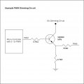
You should not need a Mega for anything you are trying to do. A single Arduino Uno and a few MOSFETs is all you should need with a power supply for your LEDs.
Ron
Code:
/*
  Fade

  This example shows how to fade an LED on pin 9 using the analogWrite()
  function.

  The analogWrite() function uses PWM, so if you want to change the pin you're
  using, be sure to use another PWM capable pin. On most Arduino, the PWM pins
  are identified with a "~" sign, like ~3, ~5, ~6, ~9, ~10 and ~11.

  This example code is in the public domain.

  http://www.arduino.cc/en/Tutorial/Fade
*/

int led = 9;           // the PWM pin the LED is attached to
int brightness = 0;    // how bright the LED is
int fadeAmount = 5;    // how many points to fade the LED by

// the setup routine runs once when you press reset:
void setup() {
  // declare pin 9 to be an output:
  pinMode(led, OUTPUT);
}

// the loop routine runs over and over again forever:
void loop() {
  // set the brightness of pin 9:
  analogWrite(led, brightness);

  // change the brightness for next time through the loop:
  brightness = brightness + fadeAmount;

  // reverse the direction of the fading at the ends of the fade:
  if (brightness <= 0 || brightness >= 255) {
    fadeAmount = -fadeAmount;
  }
  // wait for 30 milliseconds to see the dimming effect
  delay(30);
}int brightness = 0; // how bright the LED is
int fadeAmount = 5; // how many points to fade the LED by
are used in the code. We know an output PWM will determine LED brightness or intensity and we know the PWM will use a value between 0 and 255 This is an 8 bit signal (2^8). Here is what I suggest you try, load the following code:
Code:
int led = 9;           // the PWM pin the LED is attached to
int brightness = 0;    // how bright the LED is
int fadeAmount = 5;    // how many points to fade the LED by

// the setup routine runs once when you press reset:
void setup() {
  // declare pin 9 to be an output:
  pinMode(led, OUTPUT);
}

// the loop routine runs over and over again forever:
void loop() {
  // set the brightness of pin 9:
  analogWrite(led, brightness);

  // change the brightness for next time through the loop:
  brightness = brightness + fadeAmount;

  // reverse the direction of the fading at the ends of the fade:
  if (brightness <= 0 || brightness >= 255) {
    fadeAmount = -fadeAmount;
  }
  // wait for 30 milliseconds to see the dimming effect
  delay(30);
}As to a Reset of the Arduino aside from using the on board reset button there are hardware and software ways to get a reset, this is a good read on the subject, this is another good read on the subject.
You should not need a Mega for anything you are trying to do. A single Arduino Uno and a few MOSFETs is all you should need with a power supply for your LEDs.
Ron
") I was afforded the opportunity of hiring several new engineers right out of school who could write code. Heck when I went to school any code consisted of dits and dahs. We are dortunate in that we have several members who are really proficient at writing code and good at teaching it.
I was afforded the opportunity of hiring several new engineers right out of school who could write code. Heck when I went to school any code consisted of dits and dahs. We are dortunate in that we have several members who are really proficient at writing code and good at teaching it.