LED Indicator for 120VAC and 24VAC Applications

Thread Starter

cwella

Joined Jul 9, 2026
16
Hi everyone,

I’m looking for advice on the best way to run a general-purpose red LED indicator from a 120VAC supply and another LED indicator from a 24VAC supply.

I want a safe and reliable solution and was wondering whether it’s better to use pre-made AC LED indicators or build a circuit using components such as a rectifier and current-limiting resistor.

For the 120VAC application, I understand that a standard LED cannot be connected directly to mains without proper protection. For the 24VAC application, would a simple rectifier and resistor setup be suitable?

Any recommendations for suitable components or circuit designs would be appreciated.

Thanks!
 

AnalogKid

Joined Aug 1, 2013
12,188
Can't do schematics right now, so an all-text response.

The classic minimal circuit for both voltages is one series resistor to limit the peak current, plus one diode in anti-parallel with the LED to clamp the reverse voltage. Anti-parallel (or reverse-parallel) means the LED cathode is connected to the diode anode and the diode cathode is connected to the LED anode.

LED peak current is determined using Ohm's Law. Don't forget to subtract the LED forward voltage (Vf) from the mains peak voltage. Also, calculate the peak power dissipated in the resistor (using either Watt's Law or Joule's Law) and use a resistor rated for twice that amount.

Note that this is a half-wave rectifier, so the LED will be flashing at 60 Hz. This might be noticeable, particularly in you peripheral vision. To double the flash rate to 120 Hz, replace the single diode with a diode bridge.

ak
 

dl324

Joined Mar 30, 2015
18,421
I want a safe and reliable solution and was wondering whether it’s better to use pre-made AC LED indicators or build a circuit using components such as a rectifier and current-limiting resistor.
There's nothing safe about a DIYer connecting an LED to line voltage.
Any recommendations for suitable components or circuit designs would be appreciated.
This circuit will work for both mains and 24VAC. Just size the resistor appropriately to give a few mA.
1783951223007.png
For line power, I'd use a 1W resistor.

You could also replace D1 with another LED.
 

Thread Starter

cwella

Joined Jul 9, 2026
16
Thank you everyone for the responses and helpful suggestions. I appreciate you taking the time to share your knowledge and advice. It has given me some useful ideas to consider.
 

Thread Starter

cwella

Joined Jul 9, 2026
16
Many small resistors are not voltage rated for 170V, the peak of the power line voltage of 120v. You might want two resistors in series.
Good point, I appreciate you mentioning that. The voltage rating of the individual resistors is definitely something to consider, not just the resistance and power rating. Using two resistors in series would help share the voltage stress and give a better safety margin, especially with the 170V peak from a 120V AC line. Thanks for the reminder, it's a small detail that can make a big difference in reliability.
 

dl324

Joined Mar 30, 2015
18,421
Many small resistors are not voltage rated for 170V, the peak of the power line voltage of 120v. You might want two resistors in series.
Most resistors are rated for 200V.

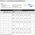
From Yaego for metal film resistors:
1783967214788.png

The resistors above that end with 'S' are the smaller variants that are rated for higher wattages:
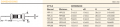
1783967303683.png
Additionally, for AC voltages, it's the RMS voltage that matters for power calculations. If he rectified and filtered, that would be different, but OP was talking about AC voltages.

EDIT: SEI data:
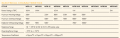
1783967745077.png
 
Last edited:

Pyrex

Joined Feb 16, 2022
514
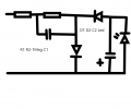
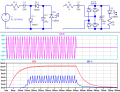
For 120VAC operation choose R1 220 Ohm 0.5W, C1 220nF 400V, C2 220uF 6.3V.
For 24VAC operation components R1 R2 C1 can be replaced to 2.4kOhm 0.5W resistor.
Capacitor C2 eliminates Led flickering
Both diodes 1N4001LED indicator.png
 
Top