LED Indicator for 120VAC and 24VAC Applications

BobTPH

Joined Jun 5, 2013
11,585
Think about a dark-colored car with a black interior, windows up, sitting in a parking lot in Arizona in August. T.h.a.t is hot.
I lived in Phoenix once, and it seemed like every year there was at least one tragic case where someone left a child in such a car. Dogs were much more common.
 

PeteHL

Joined Dec 17, 2014
585
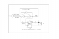
This circuit has the advantage that the voltage to the indicator LED is low and isolated from the AC current being sensed. This was important for me because I located the indicator LED at some distance away from where the circuit breaks into the AC voltage line and so the wires connecting to the LED are low voltage. Edit: D2, D3.

ISO-CURRENT-SENSE.png
 
Last edited:

B-JoJo-S

Joined Jan 3, 2026
404
So when there's AC in use the LED is lit. When there is no AC being use the LED is out. When the battery is dead there is no clear indication of the presence of AC. The TS wants to know when 120VAC is present, used or not, and to know when there is 24VAC present, used or not. These are to be indicators to let a person know when there is the presence of these voltages. It's a nice circuit though. Except that it depends on batteries. Isolated? Yes.

I don't quite get it why when current is (let's call it) forward it passes through two diodes and the AC load. But when current is reversed it only flows through one diode and the AC load. This is unfamiliar to me so I don't get why one diode in the reverse direction. The voltage drop across the diode and R1 is apparently enough to light the opto-isolator.

BTW: 1N5404 are all marked as D1. I make that kind of mistake myself from time to time.

Screenshot 2026-07-17 at 7.34.20 AM.png

Screenshot 2026-07-17 at 7.33.35 AM.png
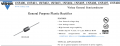
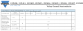
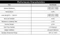
Features low forward voltage drop but the second page shows a 1.2Vf. So your circuit will oscillate between 1.2V and 2.4V going to the opto. I'm not the sharpest tool in the AAC community toolbox but it's not making a whole lot of sense to me. To "Me". Others may understand it.
 

PeteHL

Joined Dec 17, 2014
585
If there weren't diodes rectifying in both polarities in the AC line, then the load would receive only DC voltage. Two diodes rectifying in the same polarity in-series is needed to operate the opto-isolator. It is possible that the TS is interested only in whether or not an AC voltage is present. Actually in what I have installed, the 9V for lighting the LED is taken from a wall transformer at the remote location of the LED. The circuit in my post #22 is actually at least somewhat obsolete in that there are I believe now current-sensing ICs that can sense AC current when they are in close proximity to an AC line.
 

dl324

Joined Mar 30, 2015
18,432
I hope you are not saying that *all* resistors are built to this one spec. Many components intended for rugged environments are specified at +85C, +100C, and +125C.
No. I was referring to the resistors in the specifications I posted.
Note that because +70C is the ambient air temperature around the resistor and not its surface temperature, the surface temperature can be much higher - more than enough to cause real pain and blistering.
I operated a 22-ohm 1W resistor at 1W for an hour in free air. The resistor temperature was about 70C within 15 minutes and stayed there for the hour that I ran the test. Room temperature was 22C.

For SEI carbon film resistors:
1784301898788.png
My interpretation is that a resistor rated for 1000 hours at 70C ambient would operate for many thousands of hours at 22C ambient with a body temperature of 70C. According to SEI, a body temperature of 70C is less than half of the maximum.

Humans wouldn't tolerate 70C ambient temperature for long without protective equipment, and I doubt they'd be grabbing resistors and holding them for long in that environment. 70C body temperature is hot but not instantly blistering hot. I could touch the resistor, note that it was hot, remove my finger, and not have any lasting ill effects.

When I have nothing better to do, I'll repeat the experiment on a 1/4W resistor.

Incidentally, 70C (158F) isn't much hotter than when I'm cutting meat from the Thanksgiving turkey (I cut the breast from the carcass so I can crosscut the meat for tenderness and do the thigh and rest of the meat for good measure - and serve it on a plate instead of carving at the table). The meat is still hot, but not enough to cause redness (or blistering).

EDIT - correction:
Above test was conducted with a 2W resistor (the length was 0.6", not 0.48"). Did test again at 2W. Resistor body got up to 120C after about 15 minutes and stayed there for the hour I tested. Definitely hot/uncomfortable to touch, but no redness or blistering from brief touch to check temperature. Ambient temperature stayed the same (22C). I interpret that to mean that failure characteristics remained the same as the 1W dissipation test.
 
Last edited:

Pyrex

Joined Feb 16, 2022
518
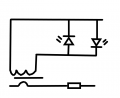
This is a current indicator with galvanic isolation, which doesn't need a battery.
A general-purpose low-power transformer (120/6V) can be used, which is connected in reverse, i.e., the primary winding is connected to the LEDs.Current indicator.png
 

dl324

Joined Mar 30, 2015
18,432
Dissipation test with a 1/4W carbon film resistor was a little surprising. It was at about 28C at the 15 minute mark and settled around 30C for the rest of the hour. I thought it would be warmer. 22C ambient.

Wasn't sure if the infrared thermometer was reading the right place, so I held it to check the temperature. Warm, but not uncomfortable.
 
Last edited:
I don't quite get it why when current is (let's call it) forward it passes through two diodes and the AC load. But when current is reversed it only flows through one diode and the AC load. This is unfamiliar to me so I don't get why one diode in the reverse direction. The voltage drop across the diode and R1 is apparently enough to light the opto-isolator.
Because this is a current-sensing circuit rather than a voltage-sensing circuit, you need a way to bypass anything from milliamps to amps while protecting the opto-coupler's input diode from both overvoltage and overcurrent.

The voltage drop across the two diodes in series, and in series with the load, is high enough to light the input diode through a small resistor, and present a relatively constant voltage source so the voltage to the input diode does not vary very much (compared to a shunt resistor) with changes in load. All of that plus adding the smallest possible voltage drop to the AC line to leave the highest possible voltage across the load while dissipating the least amount of power.

There is only one reverse diode because there is no reason for two. Ideally the reverse path would have zero ohms and zero voltage drop. There has to be something so that the other half-cycle voltage does not appear across the opto input diode and resistor.

Basically, the two forward diodes are a shunt regulator, and the single reverse diode is a clamp.

ak
 
I'd use a dedicated indicator that's rated for the correct voltage instead of trying to use the same one for both 120VAC and 24VAC. It keeps the circuit simple and makes troubleshooting easier.

A clear indicator can save a lot of time during fault finding. Before checking relays, switches, or wiring, it's always worth confirming that the incoming supply is actually present. That's often the first thing I look at when diagnosing power-related issues.
 
Hi everyone,

I’m looking for advice on the best way to run a general-purpose red LED indicator from a 120VAC supply and another LED indicator from a 24VAC supply.

I want a safe and reliable solution and was wondering whether it’s better to use pre-made AC LED indicators or build a circuit using components such as a rectifier and current-limiting resistor.

For the 120VAC application, I understand that a standard LED cannot be connected directly to mains without proper protection. For the 24VAC application, would a simple rectifier and resistor setup be suitable?

Any recommendations for suitable components or circuit designs would be appreciated.

Thanks!
You need these. https://www.amazon.com/FILN-Indicat...8-2-spons&sp_csd=d2lkZ2V0TmFtZT1zcF9hdGY&th=1
 
Top