Battery Level Indicator quest with power supplies

Status
Not open for further replies.

Thread Starter

adigitaldj1

Joined Mar 22, 2026
2
Hello!

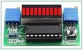
I have a circuit or circuits I have built with LM3914 Dot Bar Display Driver. I have worked on this simple circuits for weeks to get it to work right. I have done a circuit on a experimenter board with different schematics and I also purchased some to build as a kit. Every circuit acts the same. The first kit I built seemed to work ok at first but then it started acting like the one on the experimenter board.

It doesnt want to light up each led in step with the voltage. It will light up a couple then jump to almost the end. I tried a new chip, checked my solder connections etc.

What I want to know is, I am using a switch power supply and if that would affect the circuit since it should be pure dc like a battery.

This circuit is killing me being so simple and I have worked in electronics for years and built and designed many projects. I am stressed I cant get it to work for a project I am doing.

Thanks,
Kevin1774231832797.png
 

Attachments

WBahn

Joined Mar 31, 2012
32,703
I can't read that dinky schematic. Please provide a much better one.

It that supposed to be the schematic for the circuit you have in the picture? As best I can tell, there is just one pot in the schematic, but clearly two are on the board.

Please describe the troublesome behavior in more detail. Are you saying that as you start from a low voltage and increase it, that initially one LED lights up, then a second, the suddenly nearly all of them light up? Or are the middle ones not lighting up at all?

How repeatable is the behavior?

How does it behave when you use batteries as your supply? Does the behavior change, or does it still behave the same way?

Do you have any bypass capacitors in the circuit?

What current are you programming the LEDs for?

What is the current output capacity of the supply you are using?
 

Thread Starter

adigitaldj1

Joined Mar 22, 2026
2
The pictures are just for reference of what I used.

What I am trying to do is make a voltage level indicator for my F1 steering wheel and use those as like shift lights. I am making the F1 steering wheels for my slot car track. So the voltage being controlled to the track lane from the hand controller would work the shift lights level indicator. It doesn't have to be this design but this is what I started with.

Yes it lights up 1,2,3 then jumps to within 1 or 2 lights from the end. My track power supplies are switching supplies. If I add filtering where would it be added and what values? I have recently seen a circuit like that. I am also going to check if I have a linear non switching power supply.

The behavior is always the same.
Haven't tried batteries
No bypass capacitors
Leds 15ma
The power supply I have is 10amp

12v-Battery-voltage-level-indicator-lm3914-4.gif
 

WBahn

Joined Mar 31, 2012
32,703
First step would be to get some batteries and see if using those as your supply makes a difference (using a new LM3914 in case the present one has been damaged). The answer to that question determines which of two very different paths should be explored next.

Regardless of the outcome, however, it is always a good idea to provide local bypassing of the power supply.
 

WBahn

Joined Mar 31, 2012
32,703
So, all in all you don't know why?

It's not the chip, replaced it. So you don't know if the power supply can cause that or not from switching noise. It's too hard to use a battery when I need to see movement.

So, you don't know what to use for filtering the circuit? I will figure it out!

Once again, I was really afraid to post because most people want to respond that don't know sht

I will figure out my problem, thanks for wasting my time.
So, you have a problem in which a circuit's behavior changed after being in operation for some period of time, which hints at one set of potential problems. But you also say that every other circuit you build, including from kits, behaves the same way, which points to a very different set of potential problems. You don't show us a schematic of the circuit that you are actually using, but just something that is somehow a reference for what you used. You won't do a simple test that will help eliminate many of the potential issues and help focus attention on the more likely culprits. You won't use the most basic best practices, such as doing proper power supply bypassing. You think it's because you are using a switch-mode power supply, but don't provide any information about that supply that could give an indication of how much noise it might be producing. You've been working on it for weeks and can't get it to work, yet if strangers on the Internet aren't able to immediately diagnose your exact problem based solely on the initial incomplete information provided, it's because they don't know anything and are just wasting your time.

Well, don't worry, I won't be wasting any more of your time by wasting any more of my time trying to help you.
 

dl324

Joined Mar 30, 2015
18,219
The pictures are just for reference of what I used.
A schematic showing the values you're using would still be helpful.
My track power supplies are switching supplies. If I add filtering where would it be added and what values?
If the supply is well regulated, a 0.1uF ceramic cap on the power leads of the LM3914 should be sufficient.
It's not the chip, replaced it.
How do you know. Are all of the LM3914's you have from the same source? Was it a reputable source?
I posted the fucking schematic dumb ass
Your sense of entitlement is showing. You've been a member for a day and are already bad mouthing a member, a moderator no less, who's been here for over a decade.

We do this out of kindness, not for the pay. If you can't be civil, don't expect members to try to help you.
 

bassbindevil

Joined Jan 23, 2014
918
Running the LM3914 off the same supply that you're measuring looks like a problem. Also, it's helpful to have resistors in series with the LEDs. And, the chips available today are copies made by a Chinese brand, so it's possible they behave differently than the OG National Semiconductor version.
 

WBahn

Joined Mar 31, 2012
32,703
Running the LM3914 off the same supply that you're measuring looks like a problem. Also, it's helpful to have resistors in series with the LEDs. And, the chips available today are copies made by a Chinese brand, so it's possible they behave differently than the OG National Semiconductor version.
The LM3914 has programmable current sources for its outputs, so current limiting resistors are needed (though they would shift some of the heat dissipation away from the IC).
 

MisterBill2

Joined Jan 23, 2018
27,164
What has not been emphasised enough is the power to the analog LM2914!! NONE of the slot-car power packs that I have seen are filtered at all. So that is problem number one. Problem number two is all of the noise: first, unfiltered DC, THEN sliding coltacts as the cars race on the tracks, Third, DC motor commutators screaming at high RPM AND HIGH CURRENT!
This means that the voltage you are measuring HAS LOTS OF NOISE AND POOR REGULATION. AND, if the display is also powered from that source, one more noise input. VERY HIGH NOISE INDEED.
BESIDES ALL THAT, there are probably voltage drops because of thin wire. AND GROUND LOOPS, possibly.

So the first step is clean and stable power for the displays. The good news is that they do not draw much current, so the separate supply does not need a high current rating. BUT it does need a separate power system. That means no shared paths for the car power current and the display power current.
Then you can use some batteries to verify that the LED section is OK when not connected to the car power circuit.
 

MisterBill2

Joined Jan 23, 2018
27,164
I can't read that dinky schematic. Please provide a much better one.

It that supposed to be the schematic for the circuit you have in the picture? As best I can tell, there is just one pot in the schematic, but clearly two are on the board.

Please describe the troublesome behavior in more detail. Are you saying that as you start from a low voltage and increase it, that initially one LED lights up, then a second, the suddenly nearly all of them light up? Or are the middle ones not lighting up at all?

How repeatable is the behavior?

How does it behave when you use batteries as your supply? Does the behavior change, or does it still behave the same way?

Do you have any bypass capacitors in the circuit?

What current are you programming the LEDs for?

What is the current output capacity of the supply you are using?
Amazing!! I can read that little schematic well enough to understand thatthe problem is not incorrect wiring, if it is actuall assembled like the diagram shows. The needed capacitors are not there! Ifthe circuit works properly fora time, then the connections are either exactly correct, or close enough.
IF the power supply is adequate then the issue is noise. Hence the need for the capacitors, inserted so as to shunt all of the noise. THAT EFFORT is not always simple.
 
Status
Not open for further replies.
Top