LED Driver for Automotive Side Marker

Thread Starter

MB107

Joined Jul 24, 2016
400
You have 36 individual LEDs, right?

I am suggesting putting each of them in series with a resistor and then putting all 36 of those in parallel to your 12V.

You suggested putting 4 in series with a resistor then putting the nine strings of those in parallel. The reason for doing that is to reduce power used. But you don’t want to reduce power used only so you can waste it in a parallel resistor that gets very hot. Wasting at least some of the power in 36 small resistors is preferable because the heat is spread around.

SMT resistors are small and cost about a penny each.

Ideally, you could find inefficient LEDs, where, to produce the brightness, you need would take enough current to satisfy the current monitor and no parallel resistor would be needed.

You could also run higher power LEDs that way and use a neutral filter to reduce the light that gets through.

It just irks me that your solution needs a high power resistor that is large, expensive, and gets very hot. I am trying to find a solution that does not require that.
See post #66. Those strip lights are exactly as you propose each have there own resistor with each resistor LED pair wired in parallel to the 12V bus. The real problem for me, is SMT's. The 3528 LEDs are as small as I believe I can successful solder. This will be my first attempt as soldering SMT's. I did order an SMT practice kit from Amazon that I will try to solder before I try this one, but the resistors and LEDs are tiny, I have my doubt even getting 50% of them soldered correctly. But who knows, I may surprise myself. At this point if I were to try that it would have to be through hole resistors with 3528 size LEDs. I do have room for through hole resistors.

Could I really find LEDs as inefficient as an incandescent? And fairly good size that I could solder on. Do you have any examples?

The filter is a good idea. When this is done, I will have to pot all these LEDS to make them weather proof. I have been looking into potting silicone and epoxies. The optically clear is about 3 times the price of the regular so called clear. The regular clear is not so cheep either. But might help in reducing the light output. Of course all this requires trial and error.

The high power resistor is currently the standard way LEDs are installed in automotive lighting. A 10W resistor is about $3.00 and is the same resistor I would use if I were to replace the incandescent bulb shown in post #1 with an equivalent LED replacement. It's just the price of retrofitting new technology into old technology.
 

eetech00

Joined Jun 8, 2013
4,724
See post #66. It works, but not exactly ready for the automotive environment.
Maybe you bought cheap ones.
Post #66 doesn't explain....so what didn't you like about the strip light LEDs?

Also,

I don't understand why "high power" is being mentioned here. High Power LEDs are usually 300ma or higher for each LED. The LEDs you are using are standard 20ma LEDs.
 
Last edited:

BobTPH

Joined Jun 5, 2013
11,618
The strips in #66 have 3 LEDs in series, as you can see from the cut points which are every 3. Why they used 3 resistors for each series when one would do is beyond me.

It would use 3 times more current if each LED was driven by 12V. This alone brings it to only about twice the efficiency of incandescent.

As far as soldering SMT parts, 0603 are pretty easy, and I have soldered 0402 LEDs without much difficulty. The 3528 are presumably metric and would be bigger than imperial 1206, which are huge to me.

All the LEDs you have tried are designed for illumination and are therefore high efficiency. Indicator LEDs tend to be far less efficient.

Edited to add: I will bug out now, since I just seem to be annoying you.
 
Last edited:

Thread Starter

MB107

Joined Jul 24, 2016
400
Maybe you bought cheap ones.
Post #66 doesn't explain....so what didn't you like about the strip light LEDs?

Also,

I don't understand why "high power" is being mentioned here. High Power LEDs are usually 300ma or higher for each LED. The LEDs you are using are standard 20ma LEDs.
The LED strings used in post 66 were just a proof of concept. They did prove that I could take 5050 series LED lights and spread them out and reduce the voltage to get a uniform and acceptable level. High power is a relative term. In this case all the LEDs tried so far are way too bright to for the task at hand. The LED strips are also available in smaller sizes including the 3528 which are about 1/3dr the power and brightness of the 5050. With proof of concept over its time to build a circuit board.
 

Thread Starter

MB107

Joined Jul 24, 2016
400
The strips in #66 have 3 LEDs in series, as you can see from the cut points which are every 3. Why they used 3 resistors for each series when one would do is beyond me.

It would use 3 times more current if each LED was driven by 12V. This alone brings it to only about twice the efficiency of incandescent.

As far as soldering SMT parts, 0603 are pretty easy, and I have soldered 0402 LEDs without much difficulty. The 3528 are presumably metric and would be bigger than imperial 1206, which are huge to me.

All the LEDs you have tried are designed for illumination and are therefore high efficiency. Indicator LEDs tend to be far less efficient.

Edited to add: I will bug out now, since I just seem to be annoying you.
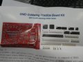
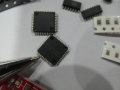
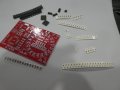
Hey Bob you are not annoying me at all. In fact you have been a big help. My main challenge will be this. This is the practice kit I purchased. I also purchased a soldering heat gun. I will see how this goes before making any decisions. Yes the 5050 and 3528 LED's are metric sizes 5mm x 5mm and 3.5mm x 2.8mm.
 

Attachments

Top