LED Driver for Automotive Side Marker

Thread Starter

MB107

Joined Jul 24, 2016
400
Any further discussion will require supplying the Wiring-Schematic for your Car.

Leave the original side-marker-bulbs attached in their original configuration, but hidden elsewhere.
Where to power the LEDs will depend on your Car's Wiring configuration.

Having Side-Markers that are brighter that the stock bulbs, isn't necessarily a bad thing.
Use just 1 LED-Board per side,
there is no need to use multiple boards when You are placing a Prismatic-Lens over them.
.
.
.
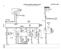
Here's the wiring diagram for the car, but no detail on what goes on inside the Exterior lamp failure monitoring unit. If I put one of those squares the light is still bright but just a square of light in the middle. I believe one square I could plug in without any problems electrically. They are 5W each square and would be replacing a 4W bulb. I would assume the monitor would have that level of tolerance.

1701402652810.png
 

LowQCab

Joined Nov 6, 2012
5,101
There's no absolute guarantees,
but my bet would be that You can use one of those LED-Boards
as a direct replacement for the original incandescent bulb,
with zero changes required, and no issues.
.
.
.
 

LesJones

Joined Jan 8, 2017
4,524
You could try putting a resistor of 68 ohms in series with each panel which should bring the total power down to about 4 watts but that will still be brighter than the original bulb as LED are about 6 times as efficient. To reduce the light output of the panels to 10% you would need a resistor of about 330 ohms in series with each panel. Just using resistors for current limiting would mean there was a sgnificant change in brightness when the voltage varies between 12 and 14 volts.

Les.
 

Thread Starter

MB107

Joined Jul 24, 2016
400
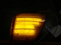
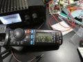
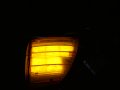
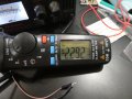
Results with the dimmer from Amazon. The dimmer works successfully in that I can get the current down below 4W, but still to bright as the dimmers lowest setting appears to only go down to 10%. One thing I will say is that the pictures are not really showing the comparison as well as your eyes. Apparently the exposure time is faster when the light is brighter causing them to look nearly the same in the pictures. So I need to be able to run less than 10% or find some other panels with LEDs on 1/2" spacing instead of 1/4" spacing. LED strips might be available like that.


0.236A-14.5V Output.JPG

0.236A-14.5V.JPG

2.292A-14.5V Output.JPG

2.292A-14.5V.JPG
 

BobTPH

Joined Jun 5, 2013
11,618
LED strips might be available like that.
I think LED strips is your solution.

Also, no need to use PWM. Just add resistance to dim. The power is the same either way, unless you lower the voltage by an efficient buck converter.
 

Thread Starter

MB107

Joined Jul 24, 2016
400
I think LED strips is your solution.

Also, no need to use PWM. Just add resistance to dim. The power is the same either way, unless you lower the voltage by an efficient buck converter.
I agree. I actually have them on order. Trick is to get the LEDs further apart but not too far that they make dots on the diffuser. I believe if I can find LED strips at 1/2" spacing and space the strips 1/2" apart. That would cut down the power and light by a factor of 4. It also gives ne better capability to conform it to the lens
 

Thread Starter

MB107

Joined Jul 24, 2016
400
Could try installing a series resistor for each LED array
I could do that as I have learned that the LEDs operate at much lower voltage thresholds than I thought. I don't know where they will cut off since my power supply only operates between 10-16V. Big resisters though which I don't have. They would need to be like 5W resisters. Lots of heat.
 

sghioto

Joined Dec 31, 2017
8,744
Heat not an issue adding the resistors with the PWM at 10%.
1 watt resistors should be adequate. Somewhere in the 10 to 15 ohm range.
The schematic posted in #12 will get down to almost a 1% duty cycle.
 
Last edited:

Thread Starter

MB107

Joined Jul 24, 2016
400
Heat not an issue adding the resistors with the PWM at 10%.
1 watt resistors should be adequate. Somewhere in the 10 to 15 ohm range.
The schematic posted in #12 will get down to almost a 1% duty cycle.
Yes PWM with the resisters would work but If I could get down to 1% with the PWM I might not need the resisters. I will try to dig out my 555 and try your circuit.
 

Thread Starter

MB107

Joined Jul 24, 2016
400
The circuit inside that dimmer I suggested as an example could be duplicated with a NE555 timer and a N channel mosfet if you wanted to construct it yourself.
View attachment 309044
EDIT: Better frequency stability with duty cycle.
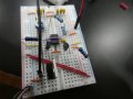
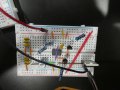
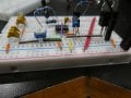
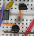
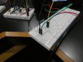
Finally got all the parts to build the circuit but not getting anything out of it. LED's don't come on at all no matter where the trim pot is set. I had to use 3 10nF and 3 2nf caps to get the equivalent of 33nf. Any idea whats wrong?

I will be playing with it for the next few days. My LED strips should also be coming in.


P1040603.JPG
P1040604.JPG

P1040602.JPG

P1040601.JPG
 

sghioto

Joined Dec 31, 2017
8,744
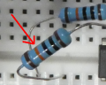
Resistors R1 and R4 are 1K, you show 100K resistors. Color code is brown-black-black-brown for 1K.
Even with 100K resistors the circuit should still work but with a limited duty cycle.
1702270001766.png

Unless the transistors are not connected correctly but can't tell which is which. Should be like in this image.
1702308608915.png


Don't need the three 2nf caps, 30nf is close enough.
 
Last edited:

Thread Starter

MB107

Joined Jul 24, 2016
400
Resistors R1 and R4 are 1K, you show 100K resistors. Color code is brown-black-black-brown for 1K.
Even with 100K resistors the circuit should still work but with a limited duty cycle.
View attachment 309752

Unless the transistors are not connected correctly but can't tell which is which. Should be like in this image.
View attachment 309781


Don't need the three 2nf caps, 30nf is close enough.
Thanks. I swapped the resistors. I verified the transistors are in the correct position. The center terminal of the pot is in the same channel with the green bar underneath it. I also replaced the purple jumper between pin 2 and 6 with a longer one in case the chip was holding the jumper too high. Still no light. Tomorrow I will start checking components. Nothing is getting hot but maybe I blew something.
 

Thread Starter

MB107

Joined Jul 24, 2016
400
Do you have a voltmeter or scope or a small LED to use as a test? Problem might be with Q3 there are easy ways to test.
I actually got it working very well. Turned out to be a bad 555. Fortunately I had a spare. I have to turn the pot all the way down to get acceptable light levels. At that point its pulling 0.17A. ~ 2.65W @ 14.5V. With a 100Ω resistor across + and - I get 3.95W. I need 4W to get my light monitor to work. So this effectively is a solution. When I try this with the strip lighting with more space between the LED's I probably will need to turn up the pot a little bit. So far nothing seems to get hot except for the 100Ω 2W resistor. so I believe I may be able to pot everything except for that resistor. The trade off will be with the lower amount of LED's the more power I will be putting across the parallel resistor to keep the power up.

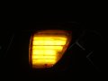
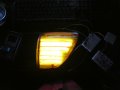
Lighting shown is at minimum and maximum on the pot. Camera tends to make them look a little less dramatic than it really is at full bright. You really cant look at it.

Thanks for your help.
P1040606.JPG

P1040605.JPG
P1040608.JPG
 

Thread Starter

MB107

Joined Jul 24, 2016
400
If you have to use the resistor upgrade to a 5 watt. At 14.5 volts the resistor is dissipating 2.1 watts.
What is this light monitor again that requires 4 watts?
I'm actually running it right now with a 2W resistor. It actually cam out to about 2.05 W required but it does get extremely hot and I believe a 5W would run a bit cooler. The light monitor warns the drive when an exterior incandescent bulb goes out. 4 watts is kind of a crap shoot. The original bulb is rated at 4W 12V, but no automotive system really runs at 12V. More like 14 to 14.5 so the real requirement might be more like 5W and I'm sure the tolerance band is fairly wide.
 

Thread Starter

MB107

Joined Jul 24, 2016
400
Are you connecting the resistor in parallel with the LEDs or from the +supply to ground?
I have it in parallel across the positive and negative terminal of the power supply. I measure current right before the resistor. Its what the lamp module would see. With 14.5V I get ~ 0.27A = 3.91W. I'm using a 2W 100Ω resistor. ~ 2W are going to the LED's and 2W going across the resistor. A 75Ω resistor might be better but I only have 50Ω and 100Ω.
 
Top