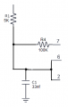
What happens if you put the resistor in parallel with the LED module? Curious if the monitor will accept it.I have it in parallel across the positive and negative terminal of the power supply.
I guess it would work but then you would be running the electronics, or at least the MFET, at much higher current. I don't see an advantage.What happens if you put the resistor in parallel with the LED module? Curious if the monitor will accept it.
The resistor would dissipate less heat. No problem for the mosfet it's rated at 49 ampsI guess it would work but then you would be running the electronics, or at least the MFET, at much higher current. I don't see an advantage.
I don't see it that way, the current goes down on the input side as I bring the duty cycle down. In fact if I run the lights at 100% I would need a 5W resistor. I can only use a 2W at minimum duty cycle. I would think it would be the same at the light array. I meant to ask you about that Mosfet. How do those little legs carry 49 amps. My car fan runs at 50A and uses 6ga wire.I really only need one for about 1 amp max. I just tried it with an IRF510N 5.6A mosfet. It works with that as well.The resistor would dissipate less heat. No problem for the mosfet it's rated at 49 amps
I'm not following that logic.I don't see it that way, the current goes down on the input side as I bring the duty cycle down. In fact if I run the lights at 100% I would need a 5W resistor.
I'm a long way off from actually testing with the monitor in place, especially with the car now in winter storage. But I do know the resistor is what people use successfully when replacing an incandescent tail light with an equivalent lower power LED.I'm not following that logic.
Every time the mosfet is activated regardless of the duty cycle it pulls max current through the LEDs which would be appx 2.5 amps at 14.5 volts for 5 arrays. The 0.17 amp measured is the average current drawn through each cycle
of the pwm signal.
My point is do you need the 100 ohm resistor?
Have you tried running the LEDs without the resistor from the monitor supply?
Geez BobTPH, sounding a little sarcastic here.Congratulations, you have managed to replace a resistor with a PWM module and a resistor! What a feat.
Yes, which indicates the PWM is the wrong way to go.here.
The TS has a legitimate concern about the lamp monitor in the vehicle. I was hoping he could test it now to confirm if a load resistor is required
What would you suggest is a better way?Yes, which indicates the PWM is the wrong way to go.
I certainly can dim the LEDS with either a buck converter or a resister in series. The question is, can I dim down to the 1% to 5% range. I thought LEDs pretty much shut off below a threshold voltage and were designed to run at the forward voltage. As far as the parallel resistor, I don't see any way around it. The parallel resistor is strictly to satisfy the lamp monitor. So it really looks to me, that I replaced 2 resistors with limited dimming capability with a PWM module and a resistor and got unlimited dimming capability.Congratulations, you have managed to replace a resistor with a PWM module and a resistor! What a feat.
1. Use LEDs not designed to put out 100 times the light he wants.What would you suggest is a better way?
#1 would be the goal if I could find them in an easy to assemble matrix form. The real problem is the number of LEDs required in order to eliminate the back reflector I need to put a tight matrix right up against the acrylic diffuser. The closer the LEDs are to the diffuser, the denser the matrix has to be to not get the dot appearance. I just got a string of LEDs in with ~1/2" spacing instead of 1/4" spacing. That will reduce the light count by a factor of 4. Using them will require me to move the leds back from the acrylic difuser. I'm hoping I can get away with 1/2" and that 1/2" will fit.1. Use LEDs not designed to put out 100 times the light he wants.
2. Dim them by adding a series resistor. Even with his current, too powerful LEDs, that is all that is needed.
Very successful. I was able to dim the LED array to very acceptable levels using a 1K resister in series. I still need a 50Ω to 100Ω resistor in parallel to bring up the input current to an acceptable level for the lamp monitor. A 2W resister is not big enough for the one in parallel. That one started to smoke but it lasted long enough to get the testing done.1. Use LEDs not designed to put out 100 times the light he wants.
2. Dim them by adding a series resistor. Even with his current, too powerful LEDs, that is all that is needed.