I can certainly get the variable with just a pot. Just tested it with different resisters. It is certainly not linear. But in my case I don't need the pot or the linear.
I can certainly get the variable with just a pot. Just tested it with different resisters. It is certainly not linear. But in my case I don't need the pot or the linear.
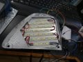
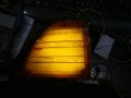
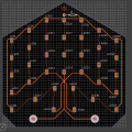
OK the situation is now under control. I was able to build a matrix of LED's using LED strips. That reduced the density of the LEDs by a factor of 4 as the spacing is double that of the last set of tiles I was using. By setting them back as much as I can and using a flexible diffuser that I can place reasonably far from the LEDs I produce a nice uniform light over the lens. A ~100Ω resistor is all I need to keep the light level down to reasonable levels. It will also require a 10W resistor to keep the lamp module from tripping.
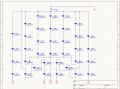
I believe I have Circuit Maker figured out. Still a few things I need to check up on. I also found the LED's I was testing with were actually three LEDs on each chip. They are called a 5050 size. I found single LED chips on what is called a 3528 size. That will make my way too bright problem into just a too bright problem and with running 4 3.2V LEDS in series the resistor to control the light output becomes much smaller. Not quite ready to order the circuit boards but getting a lot closer.
The LED circuit still isn't right.
If the battery voltage is 12v, you can only have 3-3.2v LED's (and a limiting resistor) in each series string.
What type of 3528 LED is it (so we know the forward current draw at 3.2v)? Do you have an LED datasheet?
The LED circuit still isn't right.
If the battery voltage is 12v, you can only have 3-3.2v LED's (and a limiting resistor) in each series string.
What type of 3528 LED is it (so we know the forward current draw at 3.2v)? Do you have an LED datasheet?
No car ever really has 12V unless its dead. Typically they run around 14 to 14.5V. The LED's I have coming in to try this out are these from China. So this is the only data I have. If these work well I will be purchasing similar name brand LED's with better data sheets. I ordered these in natural white.
Actually, its about 12.6v when the vehicle is off, and about 13.5-14.5 when on. When dead its 0v (or close to it).
The LED's I have coming in to try this out are these from China. So this is the only data I have. If these work well I will be purchasing similar name brand LED's with better data sheets. I ordered these in natural white.
The LED circuit still isn't right.
If the battery voltage is 12v, you can only have 3-3.2v LED's (and a limiting resistor) in each series string.
What type of 3528 LED is it (so we know the forward current draw at 3.2v)? Do you have an LED datasheet?
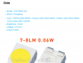
No car ever really has 12V unless its dead. Typically they run around 14 to 14.5V. The LED's I have coming in to try this out are these from China. So this is the only data I have. If these work well I will be purchasing similar name brand LED's with better data sheets. I ordered these in natural white.View attachment 311444
Yes they are also about 7-8 LM each. I only need about 35LM total. So I am going by visual appearance and will probably only need about 1 to 2 LM each.
Why do you keep buying powerful LEDs, try to restrict the current to them to make the dim, then have to add a resistor in parallel because there is not enough current drawn?
If you were to use less efficient LEDs with each one in series with a resistor powered by 12V, the current would be 4 times higher and the light would be dimmer. And perhaps it would take enough current to satisfy the monitor. You seem to be working against yourself at all stages.
Why do you keep buying powerful LEDs, try to restrict the current to them to make the dim, then have to add a resistor in parallel because there is not enough current drawn?
If you were to use less efficient LEDs with each one in series with a resistor powered by 12V, the current would be 4 times higher and the light would be dimmer. And perhaps it would take enough current to satisfy the monitor. You seem to be working against yourself at all stages.
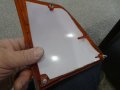
The first is the need for lots of LEDs spread out to make a uniform light being right up need the amber cover. That's required because the reflector cavity shown in the first post needs to be completely removed to make room for HID lighting. Consequently 36 LEDs of the size I have already tried are too bright, but as shown in post #66, the lighting is now uniform. However the second datasheet I posted in post #74 are very low lumen output. With 560mcd and 120° view angle that comes out to about 1.5 lumen. 36 of those would be about 50% more light than the original incandescent bulb. I will definitely be trying that LED as they would be running closer to the design power and the resistor if any would be very small to trim out the brightness.
The other resistor I will need is for the simple fact that I am replacing an incandescent bulb with an LED. That in itself is a common problem in the automotive aftermarket on any vehicle with a lamp monitor or for turn signals on a flasher. The traditional way around it has always been a resistor in parallel before the LED to just load up the circuit to the equivalent level of the original incandescent bulb installation.
So hopefully I have found an LED that is the right size to do the job effectively and just needs to be slightly adjusted for brightness and adjusted as usual to satisfy the lamp monitor.
Also this is the first time I will be surface mounting anything, so I don't want to go physically smaller in footprint.
But why do you want to put 4 in series, which reduces the current by a factor of four, then you need a parallel resistor if very high power to bring the total current back up to that of the original bulb?
It you simply put each of your 36 LEDs in series with its own resistor, It would produce the same light and the extra power would be distributed over 36 small resistors instead of one large resistor that gets very hot. You might still need the parallel resistor, but it would need to draw less current. With the right arrangement, it should be able to be eliminated completely. Efficiency is your enemy here!
But why do you want to put 4 in series, which reduces the current by a factor of four, then you need a parallel resistor if very high power to bring the total current back up to that of the original bulb?
It you simply put each of your 36 LEDs in series with its own resistor, It would produce the same light and the extra power would be distributed over 36 small resistors instead of one large resistor that gets very hot. You might still need the parallel resistor, but it would need to draw less current. With the right arrangement, it should be able to be eliminated completely. Efficiency is your enemy here!
Not sure I follow. Is that resistor-LED-resistor-LED 36 times in series or each resistor-LED pair in 36 parallel circuits directly connected to automotive voltage. I cant picture the first one working at least not with the LEDs I have been using. It would require about 35 more components involved. Likely hood of getting the brightness and power tuned just right with 36 resistors and LEDs would be pretty remote making a power trimming resistor still required. But at least it might be small enough watt resistor to put on the board.
It all sounds reasonable, but I also have to make it myself. Surface mounting for me will be difficult enough but I could put the resistors through hole. Smaller LED's that the 3528 footprint will definitely be a challenge. But the LEDs from the second data sheet I proposed in post #74 may do close enough to that. Also as far as a resistor running hot, I may not be able to mount it on the board but is shouldn't put off any more heat than the incandescent bulb shown ion post #1
I am suggesting putting each of them in series with a resistor and then putting all 36 of those in parallel to your 12V.
You suggested putting 4 in series with a resistor then putting the nine strings of those in parallel. The reason for doing that is to reduce power used. But you don’t want to reduce power used only so you can waste it in a parallel resistor that gets very hot. Wasting at least some of the power in 36 small resistors is preferable because the heat is spread around.
SMT resistors are small and cost about a penny each.
Ideally, you could find inefficient LEDs, where, to produce the brightness, you need would take enough current to satisfy the current monitor and no parallel resistor would be needed.
You could also run higher power LEDs that way and use a neutral filter to reduce the light that gets through.
It just irks me that your solution needs a high power resistor that is large, expensive, and gets very hot. I am trying to find a solution that does not require that.
I am suggesting putting each of them in series with a resistor and then putting all 36 of those in parallel to your 12V.
You suggested putting 4 in series with a resistor then putting the nine strings of those in parallel. The reason for doing that is to reduce power used. But you don’t want to reduce power used only so you can waste it in a parallel resistor that gets very hot. Wasting at least some of the power in 36 small resistors is preferable because the heat is spread around.
SMT resistors are small and cost about a penny each.
Ideally, you could find inefficient LEDs, where, to produce the brightness, you need would take enough current to satisfy the current monitor and no parallel resistor would be needed.
You could also run higher power LEDs that way and use a neutral filter to reduce the light that gets through.
It just irks me that your solution needs a high power resistor that is large, expensive, and gets very hot. I am trying to find a solution that does not require that.

 Facebook
 Google
 GitHub
 Linkedin