Kustom P50 Powered Speaker Quit

I have a recently acquired powered Speaker/PA. Kustom P50, with built-in mixer on back. Ran some audio through it several times over a few days, and then suddenly it seemed to “fizzle” or distort a little, then quit. No power LED indicator, but fuse checked ok…
Is there any burnt component or cracked solder joint?
 

LesJones

Joined Jan 8, 2017
4,534
We now seem to have all the correct power rails (+ & -32 volts and + & -15 volts.) at the power amplifier board.
IS THIS WITH THE MIXER BOARD CONNECTED TO THE POWER AMPLIFIER BOARD ?
If it is without the mixer board connected then re connect it and re check these voltages at the power amplifier board.
If all these tests are ok then check contiuity between the 5 pin connectors on the power board an the mixer board. (Test all 5 conductors.) (Do this with the power off.) Use a low resistance range (Say 200 ohm) rather than the continuity range and tell us the resistance readings for each conductor. Try to do this without moving the the boards if possible in case flexing the cable makes or breaks a connetion.
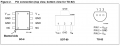
What is the part number of the opamps (8 pin DIL devices) on the mixer board ? ( So that we know the pinouts.)
Les.
 
Last edited:

bertus

Joined Apr 5, 2008
22,994
Hello,

How are R12 and R13 looking?
When the input voltage of the 7815 and 7915 where low, they had to dissipate more than rated.
They could be burned.

Bertus
 

MisterBill2

Joined Jan 23, 2018
28,113
Now I am totally puzzled! Earlier I had seen a complete circuit of the Kustom amp in a link, Now I don't find it. What happened?? Orwas the circuit removed because it was the wrong version of the amplifier??
One quick check will be on that 5-pin connector that I see in the recently arrived circuit. That has the audio input to the amplifier on pin #1. If you can connect to that pin and the amplifier "common" then you should be able to hear any iput signal and verify that the input section is working correctly. Or not.

I am still puzzled about how the original circuit I was seeing vanished.
 
Last edited:

LesJones

Joined Jan 8, 2017
4,534
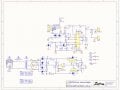
MisterBill2, The first time the schematic was shown was in post #27. From some of your comments I think you thought the amp unt was a two channel amp. At the moment Ithink the fault is one one of the 5 pin connectors or the 5 core cable as the power lamp is on the mixer board and it is not lit. It must depend on either the +15 volts or the -15 volts for it's power. We now know that the + and - 15 volts is present on the power amplifier amp board. After he has done the continuity check between the two 5 pin sockets I was going to suggest injecting a signal into pin 1 of one of the 5 pin sockets via a resistor and capacitor. I was going to suggest using the signal from the headphone socket on a battery powered radio or similar. ( I do nor think he will have a test oscillator.)

Les.
 

MisterBill2

Joined Jan 23, 2018
28,113
Inhave seen a crcuit of an amplifier that was all one assembly. That imagevanished yesterday afternoon. Other circuit immages have appeared, but they are not quite the same. so it seems that perhaps the circuit is variable. It tends to be a bit confusing. At least it confuses me, the effct on others may differ.
 

MisterBill2

Joined Jan 23, 2018
28,113
Much earlier a circuit of the power amplifier stages was available. Actually, it was probably an entire main amplifier circuit. It has since vanished. I should have done a copy and paste while it was available. Then I could share it now.
 

Thread Starter

robismod

Joined Sep 22, 2015
453
We now seem to have all the correct power rails (+ & -32 volts and + & -15 volts.) at the power amplifier board.
IS THIS WITH THE MIXER BOARD CONNECTED TO THE POWER AMPLIFIER BOARD ?
If it is without the mixer board connected then re connect it and re check these voltages at the power amplifier board.
If all these tests are ok then check contiuity between the 5 pin connectors on the power board an the mixer board. (Test all 5 conductors.) (Do this with the power off.) Use a low resistance range (Say 200 ohm) rather than the continuity range and tell us the resistance readings for each conductor. Try to do this without moving the the boards if possible in case flexing the cable makes or breaks a connetion.
What is the part number of the opamps (8 pin DIL devices) on the mixer board ? ( So that we know the pinouts.)
Les.
Thanks again. I’m out of town tonight but will be back Sunday and will dig in again.
 

Thread Starter

robismod

Joined Sep 22, 2015
453
Much earlier a circuit of the power amplifier stages was available. Actually, it was probably an entire main amplifier circuit. It has since vanished. I should have done a copy and paste while it was available. Then I could share it now.
Hmmm…that’s odd MisterBill…I haven’t deleted any images—that I’m aware of…
 

bertus

Joined Apr 5, 2008
22,994
Hello,

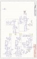
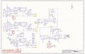
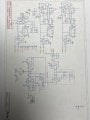
Unfortunately the designators and values of the components are unreadable on the preamp schematic.
Do you have an other format of that schematic?
I see 6 decouple capacitors, that possibly could short the powersupply.
I have circled them in the schematic:
Kustom P50 preamp decouple caps.jpeg
Bertus
 

Thread Starter

robismod

Joined Sep 22, 2015
453
Hello,

Unfortunately the designators and values of the components are unreadable on the preamp schematic.
Do you have an other format of that schematic?
I see 6 decouple capacitors, that possibly could short the powersupply.
I have circled them in the schematic:
View attachment 370693
Bertus
I thought it might be…let me see if I can get a better copy
 

LesJones

Joined Jan 8, 2017
4,534
If there were short circuit decoupling capacitors on the mixer board then you would see reduced voltage on one of the 15 rails at the power board end and one or both of the resistors before the regulators the powe boad would be hot.
The fact that the power LED is fed via a resistor from the + 15 volt rail makes me think the that the wire for + 15 volts of the 5 core cable is open circuit. (Or there is a bad connection on one of the 5 pin sockets.)
Les.
 
Top