Kustom P50 Powered Speaker Quit

activerfid

Joined May 30, 2020
35
Power off and, as Bertus suggested, pull the connector (the white 5 pin one) linking the power supply to the preamp / mixer. Power up and measure the output pins of the + / - 15V regulators (with respect to GND) at the anode of D5 (the non banded end) and cathode of D9 (banded end). Given your previous readings, something is shorted on the preamp (at a guess one of the RC4588 opamps). Ask nicely and they may send you a preamp schematic.
 

MisterBill2

Joined Jan 23, 2018
28,113
A momentary short may not have caused damage. Checking again, MORE CAREFULLY.
I find that much of the time a clip on the meter negative is a whole lot safer that measuring using two probes. Especially with a DMM that is quite happy with both polarities.
 

bertus

Joined Apr 5, 2008
22,994
Hello,

The ones i have seen where the black or yellow smd capacitors.
They often showed burn marks.
The even shorted a 50 Amp , 5 Volts supply.

Bertus
 

Thread Starter

robismod

Joined Sep 22, 2015
452
A momentary short may not have caused damage. Checking again, MORE CAREFULLY.
I find that much of the time a clip on the meter negative is a whole lot safer that measuring using two probes. Especially with a DMM that is quite happy with both polarities.
Yep…my dumbass rose up again to bite me I had been using lead adapter clips are a great help, and instead of taking a couple seconds to slip them back on I pushed ahead…arrrgggggg…I’ve gotten a little better at doing things more carefully but I still have the occasional slip-up…
 

Thread Starter

robismod

Joined Sep 22, 2015
452
Power off and, as Bertus suggested, pull the connector (the white 5 pin one) linking the power supply to the preamp / mixer. Power up and measure the output pins of the + / - 15V regulators (with respect to GND) at the anode of D5 (the non banded end) and cathode of D9 (banded end). Given your previous readings, something is shorted on the preamp (at a guess one of the RC4588 opamps). Ask nicely and they may send you a preamp schematic.
My guy at Kustom didn’t get back to me today…hopefully Monday. (I was very nice—I’m always nice in emails…I have been amazed at how nice in return many folks are when I hear back. And very helpful in most cases. Many replacement items sent to me when they really don’t have to.
 

Thread Starter

robismod

Joined Sep 22, 2015
452
Re post #35
That is why I suggested doing a continuity test rather than measuring the voltage on pins 13 & 15.
You may not have destroyed the TDA7294 as you shorted + 32 to -32 volts. do you still get about 64 to 70 volts between the left hand ends of the top and bottom diodes ? What you did could have damaged the diodes, blown the themal /overcurrent fuse in the transformer or blown the mains fuse.
Are the voltage readings in post #33 befor or after you shorted out the power supply ?
( The preamp board is just another name for the mixer board.)
Les.
Whew!
Ok Les…between bottom left diode and pin 13 yes on continuity
Between top left diode and pin 15 yes on continuity

7815:
continuity checks showed no shorts;
Pins 2 and 3 I got 15vdc

7915:
continuity checks showed no shorts;
Pin 2 and 3 I got 21vdc
 

Thread Starter

robismod

Joined Sep 22, 2015
452
Power off and, as Bertus suggested, pull the connector (the white 5 pin one) linking the power supply to the preamp / mixer. Power up and measure the output pins of the + / - 15V regulators (with respect to GND) at the anode of D5 (the non banded end) and cathode of D9 (banded end). Given your previous readings, something is shorted on the preamp (at a guess one of the RC4588 opamps). Ask nicely and they may send you a preamp schematic.
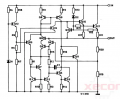
D5 non-banded end 15vdc
D9 banded end -14.7vdc
And..with preamp board (white plug) disconnected
 

Thread Starter

robismod

Joined Sep 22, 2015
452
That's not unusal has a small current is applied to the circuit from the meter when measuring ohms.
What are the input voltage readings on the 7815 and 7915 regulators?
Just now checked and:
7815 input 35vdc
7915 input 0

UPDATE: 7915 INPUT 36vdc (I had tested wrong pin)

Looking at my schematic I went to the non-banded side of D9 and got -35vdc.
 
Last edited:

activerfid

Joined May 30, 2020
35
Just now checked and:
7815 input 35vdc
7915 input 0
Looking at my schematic I went to the non-banded side of D9 and got -35vdc.
Something odd here. If the 7915 input is 0V and the anode of D9 is-35V then, assuming the schematic is correct, there is an open circuit between D9 anode and the input of the 7915, check that with a continuity test (power off). Use caution as, without any load, C16 an C18 may have voltage on them (even when powered off), you may have to discharge them with something like a 1k resistor.
 
Last edited:

LesJones

Joined Jan 8, 2017
4,534
Re your post #35 In my post #21 the continuity tests were to avoid actually measuring the voltages pins 13 and 15 of the 7294 as I could see that the pins were close together and there was the risk of shorting with the test probes. You had already meaured the voltages at the ends of the diodes so if there was continuity between pin 13 and positive ouput from the diodes and pin 15 and the negative output from the diodes then we would know the votages on pins 13 and pin 15.
It did not matter about shorting pins while contiuity testing as the power was off. In my post #40 the test for the voltage between the ends of the diodes was to see if the short had danaged the power supply section.
Les.
 

LesJones

Joined Jan 8, 2017
4,534
Re posts #52 and #54. There is a resitor (R13 330 ohms) between the -35 volts and the input to the 7915 .
When you say that the anode of D9 is at -35 v I think you have the wong pinout for the 7915. The input pin on the 7915 is the middle pin. Measure the voltage on the cathode end of D9 which is the output of th 7915. (I asked for the voltage readings on the ends of D5 and D9 in post #29.)
Les
 
Last edited:

activerfid

Joined May 30, 2020
35
Re posts #52 and #54. There is a resitor (R13 330 ohms) between the -35 volts and the input to the 7915 .
When you say that the anode of D9 is at -35 v I think you have the wong pinout for the 7915. The input pin on the 7915 is the middle pin. Measure the voltage on the cathode end of D9 which is the output of th 7915. (I asked for the voltage readings on the ends of D5 and D9 in post #29.)
Les
Yes, at this stage, to save further confusion on my part, it would be better to measure the voltages at both ends of both diodes.
 
Last edited by a moderator:

Thread Starter

robismod

Joined Sep 22, 2015
452
Re posts #52 and #54. There is a resitor (R13 330 ohms) between the -35 volts and the input to the 7915 .
When you say that the anode of D9 is at -35 v I think you have the wong pinout for the 7915. The input pin on the 7915 is the middle pin. Measure the voltage on the cathode end of D9 which is the output of th 7915. (I asked for the voltage readings on the ends of D5 and D9 in post #29.)
Les
Ah ha! Thinking back to earlier last night, I had originally had that Input pin correct. But somehow I thought I had seen a data sheet that told me it was pin 1. I remember thinking and wondering how I had it wrong, and changed it, but feeling uneasy about it…
I’ll retest when I wake up…
 
Top