Kustom P50 Powered Speaker Quit

Thread Starter

robismod

Joined Sep 22, 2015
412
I haven’t been able to find anything as far as a schematic..yet. I will try the makers of Kustom products and see about it tomorrow.
 

MrChips

Joined Oct 2, 2009
35,005
The first thing to do when trouble shooting power audio amps is to disconnect the loudspeaker otherwise the risk blowing the loudspeaker.

Use a DMM to measure the DC voltages at the speaker output and all the supply voltages.
 

MisterBill2

Joined Jan 23, 2018
27,947
The first thing to do when trouble shooting power audio amps is to disconnect the loudspeaker otherwise the risk blowing the loudspeaker.

Use a DMM to measure the DC voltages at the spea a suitable resistorin place of the speaker. To monitor the output, put a 1/4 watt 47 ohm resistor in series with the speaker. Ot maybe a 27 ohm resistor. (Those are common values is why I suggested them.
Of course there are three common kinds of audio amplifiers: Those usin vacuum tubes, having output transformers, transistor amplifiers with output transformers, transistor amplifiers without output transformers, and amplifiers using modules rather than separate components.
For actualy diagnosts of the amplifier, the first step would be to check for DC voltage across the speaker terminals.There should not be any DC voltage.
For tune-type amplifiers a visual insection to verify that all tubes "lite up" is a start, after verifying that all are in the right locations. And verify that the speakers are actually connected, and not burned out or otherwise open circuited.
 
Last edited:

Thread Starter

robismod

Joined Sep 22, 2015
412
The first thing to do when trouble shooting power audio amps is to disconnect the loudspeaker otherwise the risk blowing the loudspeaker.

Use a DMM to measure the DC voltages at the speaker output and all the supply voltages.
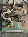
I disconnected the speakers and then was able to pull the board out…
 

LesJones

Joined Jan 8, 2017
4,516
As the power LED is not on I would start with the power supply part ofthe circuit. according to the manual (User manual)the output is 50 watts into 8 ohms the output voltge needs to be about 20 volts RMS. this requires about + & - 30 volts. so measure the voltage between the left hand ends of the top and bottom 1N5408 diodes. It should be about 60 volts DC. If this is not present then measure the voltage between the right hand ends of the bottom 2 diodes. I would expect this to be about 25 volts AC. Report the results.

Les.
 

Thread Starter

robismod

Joined Sep 22, 2015
412
As the power LED is not on I would start with the power supply part ofthe circuit. according to the manual (User manual)the output is 50 watts into 8 ohms the output voltge needs to be about 20 volts RMS. this requires about + & - 30 volts. so measure the voltage between the left hand ends of the top and bottom 1N5408 diodes. It should be about 60 volts DC. If this is not present then measure the voltage between the right hand ends of the bottom 2 diodes. I would expect this to be about 25 volts AC. Report the results.

Les.
Ok Les…many thanks!!
I have on the top and bottom 5408 diodes 71.2v…
Also, the black and white into the transformer are 120v. The 2 red coming out of transformer are 27v at each lug in front of the 5408 diodes…
(Nothing measuring at the speaker outputs)
 

LesJones

Joined Jan 8, 2017
4,516
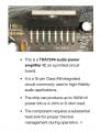
Those readings are OK. I imagine that that there is a third wire coming from the transformer secondary that is the centre tap of the 27 volt winding this will go to the the signal ground side of all the signal connections and one side of the speaker. (I think this wll be the black wire that connects to the board between the two large electrolytic capacitors.) Leave the device switched off until intil the capacitors have discharged. Then check for continuity between the left hand end of the bottom diode and pin 13 0f the TDA7294 and between and between the left hand end of the top diode and pin 15 of the TDA7294. ( Doing it this way is to avoid the risk of shorting pins together with your meter probes when the power on.) There does not look to be enough components on this board to perform the mixer function. Is there another circuit boad in the unit ? Do you have an oscilloscope to trace the signal path ? Have you checked the voltages on the output pins of the 7815 and 7915 ?

Les.
 

MisterBill2

Joined Jan 23, 2018
27,947
Often a first step in diagnostics is a careful listen to the speaker. A faint hum indicates thatat least part of the power supply is active, while total silence suggests either an input power failure or a speaker circuit open. Any slight hiss indicates that the output stage is active, and probably one or twostages before that as well.
 

Thread Starter

robismod

Joined Sep 22, 2015
412
Those readings are OK. I imagine that that there is a third wire coming from the transformer secondary that is the centre tap of the 27 volt winding this will go to the the signal ground side of all the signal connections and one side of the speaker. (I think this wll be the black wire that connects to the board between the two large electrolytic capacitors.) Leave the device switched off until intil the capacitors have discharged. Then check for continuity between the left hand end of the bottom diode and pin 13 0f the TDA7294 and between and between the left hand end of the top diode and pin 15 of the TDA7294. ( Doing it this way is to avoid the risk of shorting pins together with your meter probes when the power on.) There does not look to be enough components on this board to perform the mixer function. Is there another circuit boad in the unit ? Do you have an oscilloscope to trace the signal path ? Have you checked the voltages on the output pins of the 7815 and 7915 ?

Les.
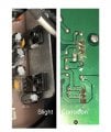
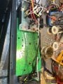
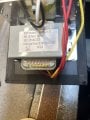
Here are a couple more pics…and I’ll work on your next suggestions shortly. Yes there is another circuit board for the mixer but I didn’t look too hard at it—just has all the mixer pots on the front side…see pic…(I’ve never used a ‘scope but I bought one of the little pocket-sized ones but have not tried to learn it yet) And still yet to track down those voltages on the 7815 and 7915….im down at my bench now and looking..
 

Attachments

Thread Starter

robismod

Joined Sep 22, 2015
412
Often a first step in diagnostics is a careful listen to the speaker. A faint hum indicates thatat least part of the power supply is active, while total silence suggests either an input power failure or a speaker circuit open. Any slight hiss indicates that the output stage is active, and probably one or twostages before that as well.
I did listen for sounds but dead as a hammer. No voltages show up on speaker outputs either. And the Power LED is still not lit after putting it back together last night…(hoping maybe a reset happened but nope)
 

MisterBill2

Joined Jan 23, 2018
27,947
OK, nothing beyond the transformer. So the next step is to check for voltage at the outputs of the transformer. That has been done and AC voltages seem reasonable. After that comes checking for voltages after the regulators. If those voltages are right, then it gets into the amplifier portion and both diagnostics and repairs get more complicated.
So one safe step is looking for fuses, since a failed fuse
 
I have on the top and bottom 5408 diodes 71.2v…
Also, the black and white into the transformer are 120v. The 2 red coming out of transformer are 27v at each lug in front of the 5408 diodes…
The two red wires are each 24VAC to the yellow. Between the two red wires are 48VAC. You said you're seeing 27V (I'll assume AC). 27 x 2 = 54V (again assuming AC). Rectified and filtered the voltage you're seeing (71.2V) filtered is the result of 54VAC x 1.414 = 76.4. Minus a few forward voltage drops the 71.2V (likely DC) seems reasonable. The power supply and rectification seems to be in working order. I think you can eliminate the PS as a source of the problem.

I see what I'm guessing at the bottom of the picture on the left is a switch. Since you're seeing 71V the switch is probably functional as well. I think you can eliminate those as potential issues.
 
OK, nothing beyond the transformer.
He said he has 71.2V. Didn't say if it was DC or AC but given the nomenclature on the transformer I'd suspect the 24V portion may be pushing out a little more than 24V. 27V was also reported. That's got to be AC. I don't think the transformer is at fault.

Transformers don't often fail. If there's an issue with the secondary (center tapped) one side of the two 24VAC outputs would be dead. You wouldn't be seeing 71V. If it were the primary then there would be nothing at the secondaries either. The TS also said the fuse was good. Here's where I have a doubt. I've seen fuses that LOOK good but are open. The TS needs to check the fuse using a continuity tester or meter. But since there's 71 volts I'm assuming the fuse is good as well. Unless the fuse is after the secondary and rectifier/filter section.
 

LesJones

Joined Jan 8, 2017
4,516
Here is a link to the datasheet on the LM7915. LM7915 datasheet
Here is a link to the datasheet on the LM7815 LM7815 datasheet
So now you know the pinout of the two regulators. I suspect that the + and - 15 volts is used on the mixer board.
Where does the power LED get it's power from ?
The manual shows that the speakers are connected in series so either one going open circuit would result in no sound. (But that would not stop the power LED from working.)
Les.
 

MisterBill2

Joined Jan 23, 2018
27,947
An easier check is to just connect a microphone and talk! "TEST" is all it takes. Either it sounds right or it doesn't ! But avoid causing feedback. But since it appears to be fairly dead, with no power LED, it seems like the logical starting point is the power supply. If the "pilot" LED went out, a reasonable area to start is the power supply. AND, given the description of the failure sequence, a quick check of the supply voltages is in order. Because it might be an output transistor. A quick check of voltages, both supply and output stages, is in order. Then check the driver area voltages.
 
Last edited:

MisterBill2

Joined Jan 23, 2018
27,947
It could be a failed DC filter capacitor, or diode.
So a quick voltage check is in order.
AND I should have suggested feeling the temperature of the output transistors and the power rectifier diodes..
 

MisterBill2

Joined Jan 23, 2018
27,947
The goodnews is still that if it DID WORK, it is probably complete and some part has failed.
So checking power supply voltages to see what changed can be a good first step.
If the power supply voltages are still close, that means probably the filter caps are still OK. Feel the black amplifier module to see if it is hot. And check the voltages across all of the polarized capacitors. They do fail in a high-leakage current manner when they fail.
Depending on how important the amplifier is to the TS, the cost of replacement parts might be "A Big Deal". So an accurate analysis matters.
 
Top