Kustom P50 Powered Speaker Quit

Thread Starter

robismod

Joined Sep 22, 2015
413
Les:
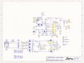
“ Then check for continuity between the left hand end of the bottom diode and pin 13 0f the TDA7294 and between and between the left hand end of the top diode and pin 15 of the TDA7294”

ok, power off. Cont. test between diode left side bottom and pin 15 is None.
Between diode left side top and pin 15 I have continuity.
(Continuing onward now )
 

Thread Starter

robismod

Joined Sep 22, 2015
413
He said he has 71.2V. Didn't say if it was DC or AC but given the nomenclature on the transformer I'd suspect the 24V portion may be pushing out a little more than 24V. 27V was also reported. That's got to be AC. I don't think the transformer is at fault.

Transformers don't often fail. If there's an issue with the secondary (center tapped) one side of the two 24VAC outputs would be dead. You wouldn't be seeing 71V. If it were the primary then there would be nothing at the secondaries either. The TS also said the fuse was good. Here's where I have a doubt. I've seen fuses that LOOK good but are open. The TS needs to check the fuse using a continuity tester or meter. But since there's 71 volts I'm assuming the fuse is good as well. Unless the fuse is after the secondary and rectifier/filter section.
Rechecked the fuse again and tested ok. Even put a spare in and tested ok.
 

sghioto

Joined Dec 31, 2017
8,734
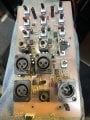
At the bottom of the mixer board I happened to try and check that resistor to the right of the multiplug—every time I touch leads of DMM to the resistor ends, the LED glows…
That's not unusal has a small current is applied to the circuit from the meter when measuring ohms.
What are the input voltage readings on the 7815 and 7915 regulators?
 
Re post #21.
Cont. test between diode left side bottom and pin 15 is None. This is correct. Diode left side bottom is the positive supply rail and pin 15 is the negative supply pin of the TDA7294. You should have tested between diode left side bottom and pin 13 ( The positive supply pin on the TDA7294.)

Les.
 

Thread Starter

robismod

Joined Sep 22, 2015
413
Re post #21.
Cont. test between diode left side bottom and pin 15 is None. This is correct. Diode left side bottom is the positive supply rail and pin 15 is the negative supply pin of the TDA7294. You should have tested between diode left side bottom and pin 13 ( The positive supply pin on the TDA7294.)

Les.
Ok I do have continuity from diode bottom left side (D7 banded end) to pin 13 on the 7294
 

Thread Starter

robismod

Joined Sep 22, 2015
413
Damn!! Got too anxious and was looking for voltage at points on the 7294…
Found 35vdc on pin 7 SUPPLY + and then went to pin 13 POWER + hands too shaky and bumped against pin 15 too…nice loud spark…reckon I’ve killed it?
 

Thread Starter

robismod

Joined Sep 22, 2015
413
Kustom told me earlier they sold two boards for this model—the preamp and the power board. 39 bucks for each. Maybe buying a Power Board might solve all of this? (And then I can keep digging into the old one )
 

LesJones

Joined Jan 8, 2017
4,517
Re post #35
That is why I suggested doing a continuity test rather than measuring the voltage on pins 13 & 15.
You may not have destroyed the TDA7294 as you shorted + 32 to -32 volts. do you still get about 64 to 70 volts between the left hand ends of the top and bottom diodes ? What you did could have damaged the diodes, blown the themal /overcurrent fuse in the transformer or blown the mains fuse.
Are the voltage readings in post #33 befor or after you shorted out the power supply ?
( The preamp board is just another name for the mixer board.)
Les.
 
Top