Just some general questions about remaking something from the past

Status
Not open for further replies.

Thread Starter

Berzerker

Joined Jul 29, 2018
623
AG said:
300 Whats (with horrible distortion) is about 40 or 50 Watts (at low distortion just before clipping).
I actually LMAO on that one AG. Maybe your avatar fits you just fine. isn't that "Scrooge McDuck" ? Baaaaa - Humbug.
Lighten up AG (!) I promise I'll be safe and test it on my front porch so I don't set the house on fire.

Which is better thermal paste or the thermal tape tabs that you cut to size? Thermal paste I'm sure gets messy.
 

Audioguru

Joined Dec 20, 2007
11,248
Car radios are advertised at 200W or 250W (Whats with lots of distortion). 40W or 50W speakers are advertised at 300 Whats.
Most car radios produce 15W x 4= 60W at low distortion just before clipping with the battery charging at 14.4V.
Some new car radios use Mosfet outputs instead of bipolar transistors for less losses so their output per channel is 22W with 10% distortion or 17W with low distortion.

Thermal tape tabs are used to insulate the collector of a power transistor from 0V. The TDA7396 has its thermal tab at 0V so insulation from 0V is not needed, then thermal paste is better.
 

Thread Starter

Berzerker

Joined Jul 29, 2018
623
AG said:
Thermal tape tabs are used to insulate the collector of a power transistor from 0V. The TDA7396 has its thermal tab at 0V so insulation from 0V is not needed, then thermal paste is better.
.
Got it thanks.
Good thing I'm not impatient and started trying to build or think everything was right in my design. The speaker magnets are 4.750 not 4.250 which is what I made them in my design. Nor can I drill a hole in the center to hold the mounting plate on. Might need to go with 5" plate instead of 4". re-do the board outline and mounting holes and move things around to match.
 

Thread Starter

Berzerker

Joined Jul 29, 2018
623
Components came in yesterday afternoon. I went ahead and ordered the ICstation converters. I can test with them to see if everything else is alright.
 

Thread Starter

Berzerker

Joined Jul 29, 2018
623
Nothing new to report. Still waiting on the ICstation converters to come in from overseas. They say it will take 10 t0 16 days so I'm kinda in pause. don't like the way I have to put two PCB's on the bottom cause no matter how I arrange them something don't look or feel right. Wires or a third PCB as a jumper from one end to the other would have to be used. So I think I'm going to wait till the converters come in and buy the same or better components place them on one PCB. Then I can arrange them anyway I want.

Ready for round two AG?
Converters 101...….;)
 
Last edited:

Audioguru

Joined Dec 20, 2007
11,248
I am waiting for you to ask, "Why doesn't my new amplifier sound louder than an ordinary car radio?"
Yours= 40W into 2 ohms. Car radio= 15W x 4= 60W.
Two of yours= 80W which sounds almost the same as the 60W from an ordinary car radio.
 

Thread Starter

Berzerker

Joined Jul 29, 2018
623
AG said:
I am waiting for you to ask, "Why doesn't my new amplifier sound louder than an ordinary car radio?"
Yours= 40W into 2 ohms. Car radio= 15W x 4= 60W.
Two of yours= 80W which sounds almost the same as the 60W from an ordinary car radio.
It's not the loudness AG. I've tried to explain it before. Some people like building race cars, some people like doing this or that.
It's just something I've always wanted to do. I wish I would have got into it earlier but life took me in another direction. and I believe in another post you said it could be as high as 60 to 65 watts per channel. The datasheet says 65 watts at 2 ohms (?). Even if it doesn't work great remember I'll just start over and build some more with something else.
 

Audioguru

Joined Dec 20, 2007
11,248
The datasheet says 65 Whats which does not say RMS, does not say "entire audio frequency range", does not say how much distortion and does not say momentary or continuous. They say "MAX" so it is probably the peak power (double the real power) of 32.5 Watts at 1kHz with 10% of awful distortion into 2 ohms with a 12.0V supply, as shown on the graph on the datasheet.

A graph of EIAJ power (a squarewave input and the amplifier output is clipping like crazy with almost as much power in the added distortion as in the program) shows 80 Whats into 2 ohms with a 16V supply.

Car radios that produce 15 Watts x 4= 60 Watts are advertised at 200 or 250 Whats.

I wish you are making a home stereo that sounds good instead of a car amplifier and speaker that have ridiculous inflated power ratings.
 

Thread Starter

Berzerker

Joined Jul 29, 2018
623
AG said:
shows 80 Whats into 2 ohms with a 16V supply.
Note to self: "can put 80 Watts on the box legally". 130 Watts if you do the math with ohms law.
We've already said that we all know that the Watts are faked, fibbed, fudged. But to me you can't keep changing the numbers to suit your post.
It's either one number or not. One minute you say 40 Watts the next it's 80 Watts. I'm going by the first few sentences in the datasheet 65 watts at 2 ohms.
edit: Got a good house stereo "500 Watts" old school pioneer (when Watts were WATTS). the one in my bedroom is 200 Watts.
 
Last edited:

Thread Starter

Berzerker

Joined Jul 29, 2018
623
Got curious and took a razor knife and cut the sticker off in the middle of the bottom of the speaker magnet. Thought just the wires went in but there (is) a screw already. Phillip's Head but I'm sure it holds the magnets, coil and wiring together. Don't think I want to mess one up before I can see how it sounds.
 

Audioguru

Joined Dec 20, 2007
11,248
With a 16V supply, the datasheet for the TDA7396 shows on a graph 42 Watts continuously at 1kHz with 1% distortion. Many people can hear 1% distortion as a rough or raspy sound. I assume that at 40 Watts the distortion is less. The text says the output power is only 20 Watts at 0.06% distortion at 1kHz. Higher frequencies produce more distortion than at 1kHz as shown on another graph at half power.

The lies about output power fool people. Peak or Max power is not the loudest parts of voice or music, instead it is the peaks of the waveforms. But you do not hear the peaks, you hear the loudest RMS parts. Peak or Max power has double the number of real RMS power.

The screw in the middle of the bottom of the speaker might hold the pole piece of the magnet, do not remove that screw.
 

Thread Starter

Berzerker

Joined Jul 29, 2018
623
AG said:
The screw in the middle of the bottom of the speaker might hold the pole piece of the magnet, do not remove that screw.
I wasn't AG. Now I'm not going to say in the future I might (?). if I fry a speaker I think it might be worth looking how they go together and if I could use it to hold the plate on.
You mentioned building a house stereo. I would love to be good enough to design and build a house stereo. But I am still learning and think that would be "A Little" over my head at this time. I have also not given up if you notice. I still read some everyday on this or that subject. Some times I read the posts or replies of other members here and wish I could answer "without looking or sounding toooo stupid". One day I will join in and try to help someone and if I can't I know several people here that can cause they helped me.
I know the amp won't be perfect but it will be something I can say "I" done.
 

Thread Starter

Berzerker

Joined Jul 29, 2018
623
finally got the ICstation converters in. Now I can get back at designing the PCB. AG was right so I will have to get someone to install the components cause they are to small to solder. Hopefully I can get them up to 100, 120 watts and at least 10 or so amps out.
Edit: opened one and I'm going to need a magnifying glass. This is going to be hard!
some of the components are about a 1/16th of an inch long and I don't see any numbers.
 
Last edited:

Thread Starter

Berzerker

Joined Jul 29, 2018
623
Don't like any shape, design "whatever you want to call it" on my PCB. Fells like I hit a wall on what I want and want to have it look like?
One way too many wires that look like their going everywhere or a PCB that's twice the size it needs to be.. I know I want to have the capacitors to lay down or it will make the space between the cover and the PCB hang way down. So now you have to place them close to the edge or create a cut out? Cut outs leave a lot of space you can't use and you have to work around them when routing. placing them on the edge and just let them hang off the side works better on routing the PCB but makes the wiring look awful. Got some of the components on the convert figured out but then thought "well why go through all this when you not sure how it will work". I have all the parts I need except the PCB's for the amp itself! I really think it's because I'm worried it won't work and I'll be disappointed. Now don't get me wrong I won't stop, I'll just regroup and try again. Or I'm just in a Lull? Haven't figured it out.
 

shortbus

Joined Sep 30, 2009
10,049
Why not worry about the 'packaging' after you get a working circuit? Why not make it in two parts and put one part on each side of the speaker magnet, with a cover over the whole thing, hiding both the speaker and the circuit in the space that just the speaker takes up?
 

Thread Starter

Berzerker

Joined Jul 29, 2018
623
Hi shortbus long time no post. it's the heatsink that causes much of the problem.

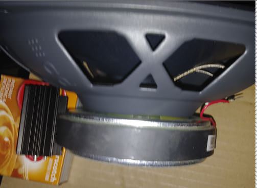
it's 2" long and I can't lay it down so it has to be vertical as the pics show. you have to remember it's 1" thick and 1.625" wide x 2" tall.
The original used the aluminum mounting plate as a heatsink (?).
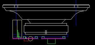
Side view.

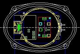
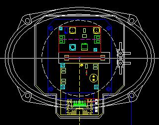
Now all my designs have to be around this! " not shouting everyone just making a point". This is why I was asking in earlier post if I could use the mounting plate as the heatsink. Top two pics show me trying to figure out if it would be better on the side or end of the speaker. Wiring would be or should I say look better with it at the end. I have tried moving the heatsink to all kinds of positions and angles till the point of my reference (design) drawing looks like I'm designing ten different types of speakers. I have erased and started over so many times I can't count them. maybe they should come up with a term for this like "design jitters". Got so far, so fast it's like hitting a brick wall.
edit: all objects in drawings are to exact dimensions.
 
Last edited:

shortbus

Joined Sep 30, 2009
10,049
it's 2" long and I can't lay it down so it has to be vertical as the pics show. you have to remember it's 1" thick and 1.625" wide x 2" tall.
Why do you think it needs to be vertical? Many heat sinks in real situations aren't oriented that way. Why does the whole thing even need to be speaker mounted? It could be a standalone 'black box' with wires going in from radio, and out to speakers.
 

Thread Starter

Berzerker

Joined Jul 29, 2018
623
shortbus said:
Why do you think it needs to be vertical? Many heat sinks in real situations aren't oriented that way. Why does the whole thing even need to be speaker mounted? It could be a standalone 'black box' with wires going in from radio, and out to speakers.
The reason it needs to be vertical is space.

Back to one of my original questions then why not just use the mounting plate as a heatsink? it's aluminum, it's 1/8" Thick x 4" Wide x 6" long. orientation came up in an earlier post. if I lay it down it takes up 1" PLUS (?) Placing it beside the magnet takes up less than 5/8" when the PCB is mounted to the plate. Mounting everything to the speaker makes installation much easier "once you mount the speaker your done mounting".
just wiring left. pic above shows how big the heatsink is to the speaker itself. If I placed it in a black box it would be just another amp (?).
Nothing would stand out and that's sure fire promotion killer! I placed it around the speaker just like the pic above in every way I could and only two looked or made sense. remember I wanted to recreate the Mindblower but had the settle for a re-design (For Now).
Edit: No the butterscotch pudding doesn't come with it!
 

shortbus

Joined Sep 30, 2009
10,049
See if you can find a heat transfer calculator for aluminum. I know though that some things use the flat plate of a box for their heat sink.
 

Thread Starter

Berzerker

Joined Jul 29, 2018
623
I know the Mindblower did it and if you take the bought heatsink and flatten it out the mounting plate would be more area.
There is a draw back? It will make the plate very hot and the way I've come up with to attach it to the bottom of the speaker is with a plastic ring that tightens around the magnet, Now this could get so hot it could melt. This is also dependent what kind of plastic you use. Microwavable dishes don't melt but I also don't think they get to 140C. Laying it flat (the IC) on the mounting plate would make a lot of the problems go away. I also don't know exactly how hot it "will" get? the datasheet only mentions what degrees it should operate within. I guess the only way to find out is test one.
 
Status
Not open for further replies.
Top